Brother International LK3-B430 Service Manual - Page 17
directions.
 |
View all Brother International LK3-B430 manuals
Add to My Manuals
Save this manual to your list of manuals |
Page 17 highlights
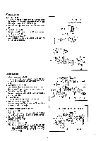
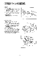
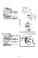
5. Tension release lever Insert the tip of it into the arm. put washer d) on tension release lever shaft (I). and tighten screw Q. The tension release leer® can easily be installed if the crank rod is shifted to the left as viewed from the rear of the machine by turning the pulley. 6. Clutch actuating lever 0 e Insert it into the arm. and connect its tip to clutch connecting rod m with screw and nut Q). 0 (I ) e 7. Clutch cam lever Fit clutch cam lever over the lower end of clutch actuating lever (D. (2) Turn the pulley until clutch cam lever roller rides on the low speed part of clutch cam 0. (3) Adjust the gap between stopper and stop cam 01 to 6 = 0.5 mm. then push clutch cam ®. lever roller to the low speed part of clutch cam and tighten bolt m. Check that there is no play in axial directions. (4) Similarly, with clutch cam lever rollers on the e low speed part of clutch cam 0. loosen two bolts with and move ball presser plate to 0 the right or left until the mark of bail presser plate 0 is in line with the center of the steel ball. and then retighten two bolts 0. I , • 0 6 .-t: O. 5ntt• • - 15 -
-
 1
1 -
2
-
3
-
4
-
5
-
6
-
7
-
8
-
9
-
10
-
11
-
 12
12 -
 13
13 -
 14
14 -
 15
15 -
 16
16 -
 17
17 -
 18
18 -
 19
19 -
 20
20 -
 21
21 -
 22
22 -
23
-
24
-
25
-
26
-
27
-
28
-
29
-
30
-
31
-
32
-
33
-
34
-
35
-
36
-
37
-
38
-
39
-
40
-
41
-
42
-
43
-
44
-
45
 |
 |
