Brother International LK3-B430 Service Manual - Page 10
Brother International LK3-B430 Manual
 |
View all Brother International LK3-B430 manuals
Add to My Manuals
Save this manual to your list of manuals |
Page 10 highlights
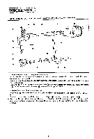
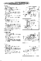
6' THREAD TENSION AND TENSION RELEASE MECHANISMS A c 0 0 0 0 e 0 0 (1) Thread Tension Mechanism The thread tension mechanism is interlocked with the power work clamp lifter mechanism. Tension release bar 0 is connected to the upper end of work clamp lifter lever 0. When the machine is started tension release pin 0 is located at the cam part 0; and immediately before the movable knife cuts the thread. tension release pinO falls into the cam part 0 to momentarily tighten tension discs 0 to prevent the upper thread from running on while thread cutting. (2) Tension Release Mechanism I. The tension release mechanism is interlocked with the clutch mechanism. When the clutch is engaged 90° before the stop cam reaches the stop position upon sewing the final stitch, tension release lever which is engaged with roller 0 conveys the motion to tension release bar 0 via tension release lever shaft 0 as fulcrum. 2. When the machine is started, tension release pin 0 is at the cam part O: and when the stop cam reaches 90° ® ®. before the stop position. tension release pin 0 rides on the cam part O to release tension discs II) and simultaneously conveys the motion to thread take-up lever via guide stud which is fixed to guide bearing thereby feeding the necessary length of thread for starting the next sewing. 0 -8-
-
 1
1 -
2
-
3
-
4
-
 5
5 -
 6
6 -
 7
7 -
 8
8 -
 9
9 -
 10
10 -
 11
11 -
 12
12 -
 13
13 -
 14
14 -
 15
15 -
16
-
17
-
18
-
19
-
20
-
21
-
22
-
23
-
24
-
25
-
26
-
27
-
28
-
29
-
30
-
31
-
32
-
33
-
34
-
35
-
36
-
37
-
38
-
39
-
40
-
41
-
42
-
43
-
44
-
45
 |
 |
