Brother International LK3-B430 Service Manual - Page 7
Brother International LK3-B430 Manual
 |
View all Brother International LK3-B430 manuals
Add to My Manuals
Save this manual to your list of manuals |
Page 7 highlights
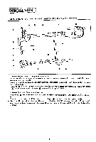
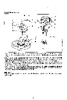
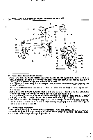
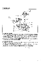
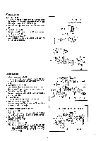
POWER WORK CLAMP LIFTER AND THREAD WIPER MECHANISMS 0- 0 010 0 C 0- 0 O (1) Power Work Clamp Lifter Mechanism I. When power actuating lever Q operates in the arrow direction, roller 0 attached to the lower end of clutch actuating lever Q is pushed up so that roller 0 disengage: from the cam part QQ of power cam 0. Thus power cam 0 contacts power pulley 0 to be driven one half of a turn. 2. Roller 0 contacts the work clamp lifter cam part @ to convey themotion toconnectingrod0 via actuatinglever shaft 0 as fulcrum. 3. Connecting rod Q is connected to connectingleverm toconvey its motion to rod A via connectinglever shaft ® al as fulcrum. 4. Rod A is connected to work clamp lifter lever to lift work clamp lifter plate ® via slide block which is fitted to work clamp lifter lever that turns about work clamp lifter lever shaft O. AFkk: ® 5. Presser arm lever which has been pushed down by work clamp lifter plate is then pushed up by presier spring ® so that work clamp ® is lowered about presser arm lever shaft as fulcrum. • 6. When work clamp lifter roller shaft ® disengages from start lever claw upon sewing the fiial stitch, roller disengages from the cam part @ so that power cam 0 half of a turn to lift work clamp O. contacts power pulley O. which drives poweecam0 one ® (2) Thread Wiper Mechanism Thread wiper rod assembly which is connected to the lower end of work clamp lifter lever conveys its motion to ® thread wiper link ® via thread wiper wiper arm 0, via thread wiper arm shaft as support fulcrum, and actuates as fulcrum. thread wiper ®, which is connected to thread • -5-
-
 1
1 -
 2
2 -
 3
3 -
 4
4 -
 5
5 -
 6
6 -
 7
7 -
 8
8 -
 9
9 -
 10
10 -
 11
11 -
 12
12 -
13
-
14
-
15
-
16
-
17
-
18
-
19
-
20
-
21
-
22
-
23
-
24
-
25
-
26
-
27
-
28
-
29
-
30
-
31
-
32
-
33
-
34
-
35
-
36
-
37
-
38
-
39
-
40
-
41
-
42
-
43
-
44
-
45
 |
 |
