Brother International LK3-B430 Service Manual - Page 18
Brother International LK3-B430 Manual
 |
View all Brother International LK3-B430 manuals
Add to My Manuals
Save this manual to your list of manuals |
Page 18 highlights
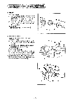
IT FEED 1. Raise the machine head. 2. Feed cam 0 With the stopper in contact with the stop cam (stop position), fit the cam lever roller into the cam groove, and install feed cam 0 with washer 0 and bolt Q in such a way that the mark ® of the feed cam meets the mark 0 of the bed. In this case, move cam lever 0 so that the cam lever roller rides on the periphery of the feed cam. 3. Tack length feed lever 0 (I) Fit slide block 0 onto tack length regulator shaft 0. (2) Fit the roller into the cam groove. move it in the arrow direction, and fit slide block 0 into the groove. (3) Insert pinch sleeve 0 into the matching hole in the bed, fit washer m onto tack length feed ® lever shaft 0, and tighten it with bolts. (4) Lead the wick out of the tack length feed lever Q to the leafspring0, and tightenit with screw m. O 0- 0-- 4 At. - A0 0 O 00 POWER WORK CLAMP LIFTER I. Power cam 0 ( I) Fit washer 0 onto the drive lever shaft. (2) Fit washer 0, spring 0 and washer 0 onto the power pulley shaft. (3) Fit drive lever 0 onto the drive lever shaft and power pulley shaft, and put washer and stop rings and Q on. (4) Hook drive lever spring a) to the pin on the drive lever. ®. 2. Power pulley Install it with washer and screw 0 00 0 0 0 000 I I 0 • 0 - 16 -
-
 1
1 -
2
-
3
-
4
-
5
-
6
-
7
-
8
-
9
-
10
-
11
-
12
-
 13
13 -
 14
14 -
 15
15 -
 16
16 -
 17
17 -
 18
18 -
 19
19 -
 20
20 -
 21
21 -
 22
22 -
 23
23 -
24
-
25
-
26
-
27
-
28
-
29
-
30
-
31
-
32
-
33
-
34
-
35
-
36
-
37
-
38
-
39
-
40
-
41
-
42
-
43
-
44
-
45
 |
 |
