Brother International LK3-B430 Service Manual - Page 5
Chanem
 |
View all Brother International LK3-B430 manuals
Add to My Manuals
Save this manual to your list of manuals |
Page 5 highlights
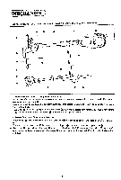
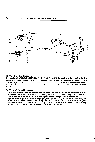
CMEcHANEM ,.* NEEDL BAR, THREAD TAKE-UP LEVER, LOWER SHAFT, SHUTTLE MECHANISMS 0 0 A 0 9 0 0- - 0- - - 0 (1) Needle Bar and Thread Take-up Lever Mechanism I. When pulle 0 turns in the arrow direction. its rotating motion is conveyed to counter weight Q which is connected to upper shaft 0. 2. Needle bar crank 0 is attached to counter weight 0 so that needle bar clamp 0 is moved up and down via needle bar crank rod 0. 3. Needle bar O. which is gripped by needle bar clamp 0. is guided by needle bar bushing U 0. needle bar bushing D 0 and needle bar guide slide block m to smoothly run up and down. (2) Lower Shaft and Shuttle Mechanism moves 4. When pulley O turns in the arrow direction. crank rode up and down via the crank part ® of the upper e. shaft. 5. The louer end of crank rod ® is connected to rock gear and rocks about rock gear shaft (1). ® e 6. Rock cear s engages lower shaft gear ® which is fixed to lower shaft O. and turns lower shaft one half of a turn. Similarly. its motion is cons eyed to driver attached to the tip of lower shaft to drive shuttle one half of a turn. -3-
-
 1
1 -
 2
2 -
 3
3 -
 4
4 -
 5
5 -
 6
6 -
 7
7 -
 8
8 -
 9
9 -
 10
10 -
 11
11 -
12
-
13
-
14
-
15
-
16
-
17
-
18
-
19
-
20
-
21
-
22
-
23
-
24
-
25
-
26
-
27
-
28
-
29
-
30
-
31
-
32
-
33
-
34
-
35
-
36
-
37
-
38
-
39
-
40
-
41
-
42
-
43
-
44
-
45
 |
 |
