Brother International PEDESIGN 6.0 Users Manual - English - Page 242
List of Tool Box Buttons
 |
View all Brother International PEDESIGN 6.0 manuals
Add to My Manuals
Save this manual to your list of manuals |
Page 242 highlights
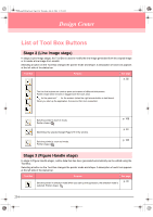
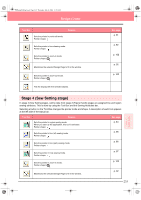
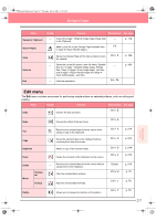
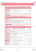
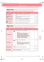
PeDesignV6Eng.book Page 234 Thursday, July 8, 2004 11:59 AM Design Center List of Tool Box Buttons Stage 2 (Line Image stage) In stage 2 (Line Image stage), the Tool Box is used to modify the line image generated from the original image or to create a line image from scratch. Selecting a button on the Tool Box changes the pointer mode and shape. A description of each tool appears at the left side of the status bar. Tool Box Purpose See page p. 32 The five first buttons are used as pens and erasers of different thicknesses. Pointer shape when moved or dragged over the work area: for the pens and for the erasers (when the right mouse button is held down). When you start up the application, the second Pen tool is selected. Sets the pointer in zoom-in mode. Pointer shape: Maximizes the selected Design Page to fit in the window. Sets the pointer in zoom-out mode. Pointer shape: p. 102 p. 34 p. 102 Stage 3 (Figure Handle stage) In stage 3 (Figure Handle stage), outline data that has been generated automatically can be edited using the Tool Box. Selecting a button on the Tool Box changes the pointer mode and shape. A description of each tool appears at the left side of the status bar. Tool Box Purpose See page Sets the pointer in selection mode.When you start up the application, the selection mode is selected. Pointer shape: p. 78 234
-
 1
1 -
2
-
3
-
4
-
5
-
6
-
7
-
8
-
9
-
10
-
11
-
12
-
13
-
14
-
15
-
16
-
17
-
18
-
19
-
20
-
21
-
22
-
23
-
24
-
25
-
26
-
27
-
28
-
29
-
30
-
31
-
32
-
33
-
34
-
35
-
36
-
37
-
38
-
39
-
40
-
41
-
42
-
43
-
44
-
45
-
46
-
47
-
48
-
49
-
50
-
51
-
52
-
53
-
54
-
55
-
56
-
57
-
58
-
59
-
60
-
61
-
62
-
63
-
64
-
65
-
66
-
67
-
68
-
69
-
70
-
71
-
72
-
73
-
74
-
75
-
76
-
77
-
78
-
79
-
80
-
81
-
82
-
83
-
84
-
85
-
86
-
87
-
88
-
89
-
90
-
91
-
92
-
93
-
94
-
95
-
96
-
97
-
98
-
99
-
100
-
101
-
102
-
103
-
104
-
105
-
106
-
107
-
108
-
109
-
110
-
111
-
112
-
113
-
114
-
115
-
116
-
117
-
118
-
119
-
120
-
121
-
122
-
123
-
124
-
125
-
126
-
127
-
128
-
129
-
130
-
131
-
132
-
133
-
134
-
135
-
136
-
137
-
138
-
139
-
140
-
141
-
142
-
143
-
144
-
145
-
146
-
147
-
148
-
149
-
150
-
151
-
152
-
153
-
154
-
155
-
156
-
157
-
158
-
159
-
160
-
161
-
162
-
163
-
164
-
165
-
166
-
167
-
168
-
169
-
170
-
171
-
172
-
173
-
174
-
175
-
176
-
177
-
178
-
179
-
180
-
181
-
182
-
183
-
184
-
185
-
186
-
187
-
188
-
189
-
190
-
191
-
192
-
193
-
194
-
195
-
196
-
197
-
198
-
199
-
200
-
201
-
202
-
203
-
204
-
205
-
206
-
207
-
208
-
209
-
210
-
211
-
212
-
213
-
214
-
215
-
216
-
217
-
218
-
219
-
220
-
221
-
222
-
223
-
224
-
225
-
226
-
227
-
228
-
229
-
230
-
231
-
232
-
233
-
234
-
235
-
236
-
 237
237 -
 238
238 -
 239
239 -
 240
240 -
 241
241 -
 242
242 -
 243
243 -
 244
244 -
 245
245 -
 246
246 -
 247
247 -
248
-
249
-
250
-
251
-
252
-
253
-
254
-
255
-
256
-
257
-
258
-
259
-
260
-
261
-
262
-
263
-
264
-
265
-
266
-
267
-
268
-
269
-
270
-
271
-
272
 |
 |
