Compaq Armada E700 Compaq ArmadaStation EM Maintenance and Service Guide - Page 32
Disassembly Sequence Chart
 |
View all Compaq Armada E700 manuals
Add to My Manuals
Save this manual to your list of manuals |
Page 32 highlights
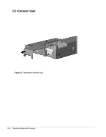
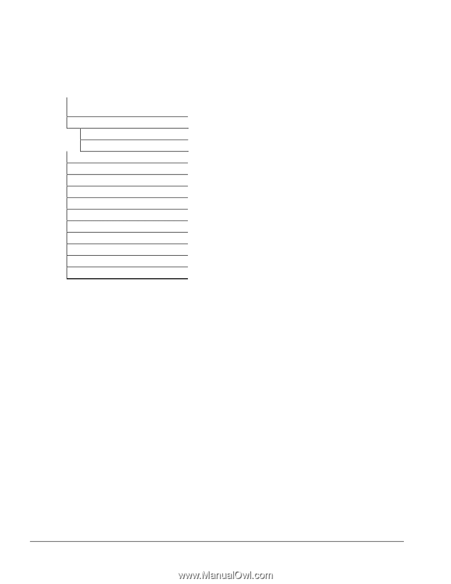
5.2 Disassembly Sequence Chart Use the chart below to determine the section number and disassembly sequence for removing components from the Compaq ArmadaStation EM. 5.3 Preparing the Expansion Base for Disassembly 5.4 External Components Expansion Base Feet Tray 5.5 Connector Cover 5.6 Rear Bezel 5.7 PCI Expansion Boards 5.8 Top Cover 5.9 Half-Height Bay 5.10 Left Speaker 5.11 MultiBay 5.12 Control Panel 5.13 Mechanism Assembly 5.14 Power Supply 5.15 Backplane Figure 5-2. Expansion Base Disassembly Sequence 5-2 Removal and Replacement Procedures
-
 1
1 -
2
-
3
-
4
-
5
-
6
-
7
-
8
-
9
-
10
-
11
-
12
-
13
-
14
-
15
-
16
-
17
-
18
-
19
-
20
-
21
-
22
-
23
-
24
-
25
-
26
-
 27
27 -
 28
28 -
 29
29 -
 30
30 -
 31
31 -
 32
32 -
 33
33 -
 34
34 -
 35
35 -
 36
36 -
 37
37 -
38
-
39
-
40
-
41
-
42
-
43
-
44
-
45
-
46
-
47
-
48
-
49
-
50
-
51
-
52
-
53
-
54
-
55
-
56
-
57
-
58
-
59
-
60
-
61
-
62
-
63
-
64
-
65
-
66
-
67
-
68
-
69
-
70
-
71
-
72
-
73
-
74
 |
 |
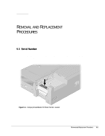
5-2
Removal and Replacement Procedures
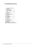
5.2
Disassembly Sequence Chart
Use the chart below to determine the section number and disassembly sequence for
removing components from the Compaq ArmadaStation EM.
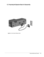
5.3
Preparing the Expansion Base for
Disassembly
5.4
External Components
Expansion Base Feet
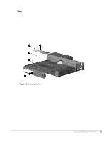
Tray
5.5
Connector Cover
5.6
Rear Bezel
5.7
PCI Expansion Boards
5.8
Top Cover
5.9
Half-Height Bay
5.10
Left Speaker
5.11
MultiBay
5.12
Control Panel
5.13
Mechanism Assembly
5.14
Power Supply
5.15
Backplane
Figure 5-2.
Expansion Base Disassembly Sequence