Compaq Armada E700 Compaq ArmadaStation EM Maintenance and Service Guide - Page 36
Connector Cover, Reverse the removal procedure described above to install the connector cover.
 |
View all Compaq Armada E700 manuals
Add to My Manuals
Save this manual to your list of manuals |
Page 36 highlights
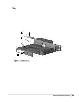
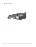
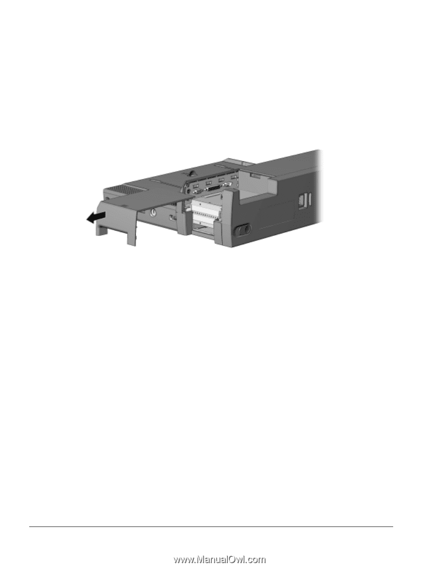
5.5 Connector Cover 1. Prepare the expansion base for disassembly (Section 5.3). 2. Position the expansion base so the rear bezel faces forward. 3. Slide the connector cover to the left and remove it (Figure 5-6). Figure 5-6. Removing the Connector Cover Reverse the removal procedure described above to install the connector cover. 5-6 Removal and Replacement Procedures
-
 1
1 -
2
-
3
-
4
-
5
-
6
-
7
-
8
-
9
-
10
-
11
-
12
-
13
-
14
-
15
-
16
-
17
-
18
-
19
-
20
-
21
-
22
-
23
-
24
-
25
-
26
-
27
-
28
-
29
-
30
-
 31
31 -
 32
32 -
 33
33 -
 34
34 -
 35
35 -
 36
36 -
 37
37 -
 38
38 -
 39
39 -
 40
40 -
 41
41 -
42
-
43
-
44
-
45
-
46
-
47
-
48
-
49
-
50
-
51
-
52
-
53
-
54
-
55
-
56
-
57
-
58
-
59
-
60
-
61
-
62
-
63
-
64
-
65
-
66
-
67
-
68
-
69
-
70
-
71
-
72
-
73
-
74
 |
 |
5-6
Removal and Replacement Procedures
5.5
Connector Cover
1. Prepare the expansion base for disassembly (Section 5.3).
2. Position the expansion base so the rear bezel faces forward.
3. Slide the connector cover to the left and remove it (Figure 5-6).
Figure 5-6.
Removing the Connector Cover
Reverse the removal procedure described above to install the connector cover.