Compaq Armada E700 Compaq ArmadaStation EM Maintenance and Service Guide - Page 72
Index - service manual
 |
View all Compaq Armada E700 manuals
Add to My Manuals
Save this manual to your list of manuals |
Page 72 highlights
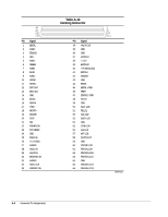
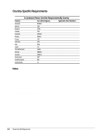
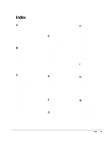
Index A AC power cord 3-conductor, B-1 activity lights, 1-6 additional information, vi alignment guides illustrated, 1-3 altitude specification, 6-1 B backplane illustrated, 3-2 removing, 5-31 spare part number, 3-3 base cover illustrated, 3-2 spare part number, 3-3 bezel cage illustrated, 3-2 spare part number, 3-3 C cables, 4-7 CD-ROM drive/audio cable connecting, 5-21 illustrated, 3-2, 3-5 components, 1-3 front panel, 1-3 illustrated, 3-2 rear panel, 1-5 right side, 1-4 spare part numbers, 3-3 top, 1-3 computer eject button illustrated, 1-4 connector cover illustrated, 3-2, 3-4 connectors, 4-7 control panel illustrated, 3-2 removing, 5-26 spare part number, 3-3 D depth specification, 6-1 disassembly sequence chart, 5-2 disconnecting power, 5-3 diskette drive, 1-3 cable connecting, 5-19 illustrated, 3-2, 3-5 docking connector illustrated, 1-3 pinout, A-4 drive power cable illustrated, 3-5 E electrostatic discharge, 4-1 preventing damage, 4-2 expansion board installing, 5-9 expansion slot cover removing, 5-10 external components, 5-4 F features, 1-1 feet installing, 5-4 G generating static, 4-2 grounding equipment, 4-4 methods, 4-3 workstations, 4-4 H half-height bay illustrated, 1-3 bays, 1-7, 5-14 hard drive cable connecting, 5-20 illustrated, 3-2, 3-5 headphone jack illustrated, 1-4 pinout, A-1 height specification, 6-1 humidity (relative) specification, 6-1 I information locating additional, vi ISA expansion board, 1-7 K keyboard carbon spare part number, 3-6 connector illustrated, 1-5 pinout, A-2 keylock illustrated, 1-4 M Maintenance and Service Guide spare part number, 3-6 manual release lever, 5-8 mechanism assembly illustrated, 3-2 removing, 5-27 spare part number, 3-3 Index I-1
-
 1
1 -
2
-
3
-
4
-
5
-
6
-
7
-
8
-
9
-
10
-
11
-
12
-
13
-
14
-
15
-
16
-
17
-
18
-
19
-
20
-
21
-
22
-
23
-
24
-
25
-
26
-
27
-
28
-
29
-
30
-
31
-
32
-
33
-
34
-
35
-
36
-
37
-
38
-
39
-
40
-
41
-
42
-
43
-
44
-
45
-
46
-
47
-
48
-
49
-
50
-
51
-
52
-
53
-
54
-
55
-
56
-
57
-
58
-
59
-
60
-
61
-
62
-
63
-
64
-
65
-
66
-
 67
67 -
 68
68 -
 69
69 -
 70
70 -
 71
71 -
 72
72 -
 73
73 -
 74
74
 |
 |