Compaq Armada E700 Compaq ArmadaStation EM Maintenance and Service Guide - Page 41
the documentation included with the board for connection information.
 |
View all Compaq Armada E700 manuals
Add to My Manuals
Save this manual to your list of manuals |
Page 41 highlights
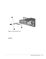
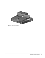
6. Align the bracket on the left side of the expansion board – with the expansion slot on the left side of the expansion base — (Figure 5-11). 7. Push the expansion board into the expansion slot until the connector is seated. 8. Secure the expansion board to the base cover by installing the screw ˜ removed in Step 4. Figure 5-11. Installing an Expansion Board Reverse the installation procedure described above to remove an expansion board. Once an expansion board has been installed, its internal connector can be accessed on the lower right side of the expansion base. If the expansion board has a cable, refer to the documentation included with the board for connection information. IMPORTANT: If a PCI CardBus Reader has been installed, PC Cards must be inserted label side down into the PC Card slot. For more information about using PC Cards, refer to the printed computer Reference Guide included with the computer. Removal and Replacement Procedures 5-11
-
 1
1 -
2
-
3
-
4
-
5
-
6
-
7
-
8
-
9
-
10
-
11
-
12
-
13
-
14
-
15
-
16
-
17
-
18
-
19
-
20
-
21
-
22
-
23
-
24
-
25
-
26
-
27
-
28
-
29
-
30
-
31
-
32
-
33
-
34
-
35
-
 36
36 -
 37
37 -
 38
38 -
 39
39 -
 40
40 -
 41
41 -
 42
42 -
 43
43 -
 44
44 -
 45
45 -
 46
46 -
47
-
48
-
49
-
50
-
51
-
52
-
53
-
54
-
55
-
56
-
57
-
58
-
59
-
60
-
61
-
62
-
63
-
64
-
65
-
66
-
67
-
68
-
69
-
70
-
71
-
72
-
73
-
74
 |
 |
