Compaq Armada E700 Compaq ArmadaStation EM Maintenance and Service Guide - Page 66
Table A-6, External Monitor Connector, Table A-7, Stereo Line-out Jack, Table A-8, Stereo Line-in
 |
View all Compaq Armada E700 manuals
Add to My Manuals
Save this manual to your list of manuals |
Page 66 highlights
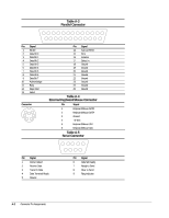
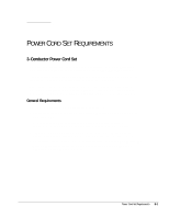
Pin Signal 1 Red Analog 2 Green Analog 3 Blue Analog 4 Monitor ID Bit 2 5 Ground 6 Ground 7 Ground 8 Ground Connector 12 Connector 12 Table A-6 External Monitor Connector 5 43 21 10 KEY 8 7 6 15 14 13 12 11 Pin Signal 9 +5 Volt Supply 10 Ground 11 Monitor ID Bit 0 12 Monitor ID Bit 1 (SDA) 13 Horizontal Sync 14 Vertical Sync 15 Monitor ID Bit 3 (SCL) Table A-7 Stereo Line-out Jack Pin Signal 1 Audio out 2 Ground Table A-8 Stereo Line-in Jack Pin Signal 1 Audio in 2 Ground Connector Pin Assignments A-3
-
 1
1 -
2
-
3
-
4
-
5
-
6
-
7
-
8
-
9
-
10
-
11
-
12
-
13
-
14
-
15
-
16
-
17
-
18
-
19
-
20
-
21
-
22
-
23
-
24
-
25
-
26
-
27
-
28
-
29
-
30
-
31
-
32
-
33
-
34
-
35
-
36
-
37
-
38
-
39
-
40
-
41
-
42
-
43
-
44
-
45
-
46
-
47
-
48
-
49
-
50
-
51
-
52
-
53
-
54
-
55
-
56
-
57
-
58
-
59
-
60
-
 61
61 -
 62
62 -
 63
63 -
 64
64 -
 65
65 -
 66
66 -
 67
67 -
 68
68 -
 69
69 -
 70
70 -
 71
71 -
72
-
73
-
74
 |
 |
Connector Pin Assignments
A-3
Table A-6
External Monitor Connector
1
6
2
3
8
7
4
5
10
KEY
11
12
13
14
15
Pin
Signal
Pin
Signal
1
Red Analog
9
+5 Volt Supply
2
Green Analog
10
Ground
3
Blue Analog
11
Monitor ID Bit 0
4
Monitor ID Bit 2
12
Monitor ID Bit 1 (SDA)
5
Ground
13
Horizontal Sync
6
Ground
14
Vertical Sync
7
Ground
15
Monitor ID Bit 3 (SCL)
8
Ground
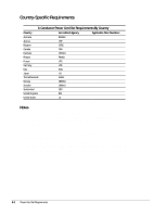
Table A-7
Stereo Line-out Jack
Connector
Pin
Signal
1
2
1
2
Audio out
Ground
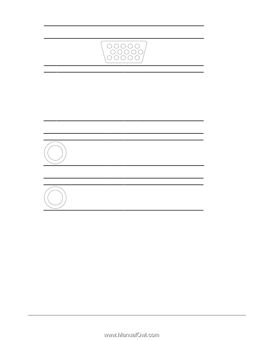
Table A-8
Stereo Line-in Jack
Connector
Pin
Signal
1
2
1
2
Audio in
Ground