Compaq Armada E700 Compaq ArmadaStation EM Maintenance and Service Guide - Page 9
ArmadaStation EM Components, Table 1-2 - hard drive
 |
View all Compaq Armada E700 manuals
Add to My Manuals
Save this manual to your list of manuals |
Page 9 highlights
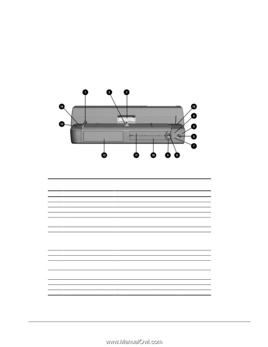
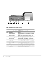
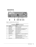
1.2 ArmadaStation EM Components The external components on the front of the ArmadaStation EM are shown in Figure 1-2 and described in Table 1-2. Figure 1-2. ArmadaStation EM Front Components Table 1-2 ArmadaStation EM Front Components Item Description Function 1 Alignment guides 2 Retaining latch 3 Docking connector 4 Top MultiBay Light 5 Power/suspend light 6 Suspend button 7 Bottom MultiBay light Align the computer onto the ArmadaStation EM. Secures the computer to the ArmadaStation EM. Connects the computer to the ArmadaStation EM. Indicates a drive in the top MultiBay is being accessed. When lit, indicates the ArmadaStation EM is on. When blinking, indicates the ArmadaStation EM is in Suspend. Initiates and exits Suspend. When lit, indicates a drive in the bottom MultiBay is being accessed or a battery pack in the bottom MultiBay is charging or waiting to be charged. When blinking, indicates a battery pack in the bottom MultiBay has reached a low battery condition. 8 Top MultiBay release button Releases a drive from the top MultiBay. 9 Bottom MultiBay release button Releases a drive from the bottom MultiBay. 10 Bottom MultiBay Supports a removable DVD-ROM drive, CD-ROM drive, diskette drive, SuperDisk LS-120 drive, hard drive, or extra battery pack. 11 Top MultiBay Supports a removable DVD-ROM drive, CD-ROM drive, SuperDisk LS-120 drive, or hard drive. 12 Half-height bay Supports an optional industry standard half-height device. 13 Monitor support cover recess Supports the front leg of the monitor support cover. 14 Stereo speakers (2) Produce stereo sound. Product Description 1-3
-
 1
1 -
2
-
3
-
 4
4 -
 5
5 -
 6
6 -
 7
7 -
 8
8 -
 9
9 -
 10
10 -
 11
11 -
 12
12 -
 13
13 -
 14
14 -
15
-
16
-
17
-
18
-
19
-
20
-
21
-
22
-
23
-
24
-
25
-
26
-
27
-
28
-
29
-
30
-
31
-
32
-
33
-
34
-
35
-
36
-
37
-
38
-
39
-
40
-
41
-
42
-
43
-
44
-
45
-
46
-
47
-
48
-
49
-
50
-
51
-
52
-
53
-
54
-
55
-
56
-
57
-
58
-
59
-
60
-
61
-
62
-
63
-
64
-
65
-
66
-
67
-
68
-
69
-
70
-
71
-
72
-
73
-
74
 |
 |