Compaq Armada E700 Compaq ArmadaStation EM Maintenance and Service Guide - Page 55
Slide the MultiBay forward, these screws in the correct locations when reinstalling the MultiBay.
 |
View all Compaq Armada E700 manuals
Add to My Manuals
Save this manual to your list of manuals |
Page 55 highlights
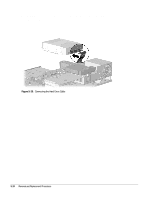
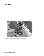
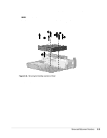
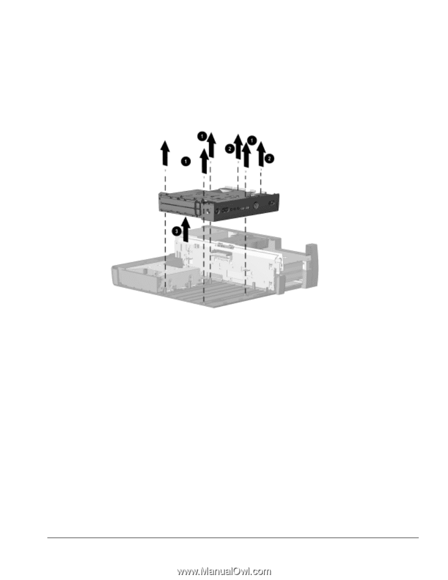
7. Remove the six screws – and — that secure the MultiBay and control panel to the base cover (Figure 5-25). NOTE: The screws removed in this step are two different sizes: four screws – are Torx T10 screws; the other two screws — are Torx T15 screws. Be sure to install these screws in the correct locations when reinstalling the MultiBay. 8. Slide the MultiBay forward ˜ and then left it out of the base cover ™. Figure 5-25. Removing the MultiBay and Control Panel Reverse the removal procedure described above to install the MultiBay and control panel into the base cover. Removal and Replacement Procedures 5-25
-
 1
1 -
2
-
3
-
4
-
5
-
6
-
7
-
8
-
9
-
10
-
11
-
12
-
13
-
14
-
15
-
16
-
17
-
18
-
19
-
20
-
21
-
22
-
23
-
24
-
25
-
26
-
27
-
28
-
29
-
30
-
31
-
32
-
33
-
34
-
35
-
36
-
37
-
38
-
39
-
40
-
41
-
42
-
43
-
44
-
45
-
46
-
47
-
48
-
49
-
 50
50 -
 51
51 -
 52
52 -
 53
53 -
 54
54 -
 55
55 -
 56
56 -
 57
57 -
 58
58 -
 59
59 -
 60
60 -
61
-
62
-
63
-
64
-
65
-
66
-
67
-
68
-
69
-
70
-
71
-
72
-
73
-
74
 |
 |
Removal and Replacement Procedures
5-25
7. Remove the six screws
and
that secure the MultiBay and control panel to the
base cover (Figure 5-25).
NOTE:
The screws removed in this step are two different sizes: four screws
are
Torx T10 screws; the other two screws
are Torx T15 screws. Be sure to install
these screws in the correct locations when reinstalling the MultiBay.
8. Slide the MultiBay forward
and then left it out of the base cover
.
Figure 5-25.
Removing the MultiBay and Control Panel
Reverse the removal procedure described above to install the MultiBay and control
panel into the base cover.