Dell Dimension E520 Owner's Manual - Page 111
Video, Network adapter, Audio, Serial ATA, FlexBay Drive, Floppy drive, PCI 2.3, PCI Express x1 - blinking amber light
 |
View all Dell Dimension E520 manuals
Add to My Manuals
Save this manual to your list of manuals |
Page 111 highlights
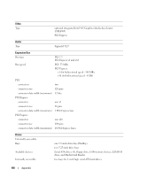
Connectors External connectors: Video Network adapter USB Audio System board connectors: Serial ATA FlexBay Drive Floppy drive Fan PCI 2.3 PCI Express x1 PCI Express x16 15-hole connector RJ-45 connector two front-panel and six back-panel USB 2.0-compliant connectors six connectors for 7.1 support four 7-pin connectors one USB 10-pin header for optional Media Card Reader (3.5-inch bay device) one 33-pin connector one 5-pin connectors two 120-pin connectors one 36-pin connector one 164-pin connector Controls and Lights Power button push button Power light green light - Blinking green in sleep state; solid green for poweron state. amber light - Blinking amber indicates a problem with the power supply inside the computer. If the system cannot boot and there is a solid amber light, this indicates a problem with the system board (see "Power Problems" on page 41). Hard-drive access light green Link integrity light (on integrated network adapter) green light - A good connection exists between the network and the computer. off (no light) - The computer is not detecting a physical connection to the network. Activity light (on integrated network yellow blinking light adapter) Diagnostic lights four lights on the front panel (see "Diagnostic Lights" on page 47.) Standby power light STBYLED on the system board Appendix 111
-
 1
1 -
2
-
3
-
4
-
5
-
6
-
7
-
8
-
9
-
10
-
11
-
12
-
13
-
14
-
15
-
16
-
17
-
18
-
19
-
20
-
21
-
22
-
23
-
24
-
25
-
26
-
27
-
28
-
29
-
30
-
31
-
32
-
33
-
34
-
35
-
36
-
37
-
38
-
39
-
40
-
41
-
42
-
43
-
44
-
45
-
46
-
47
-
48
-
49
-
50
-
51
-
52
-
53
-
54
-
55
-
56
-
57
-
58
-
59
-
60
-
61
-
62
-
63
-
64
-
65
-
66
-
67
-
68
-
69
-
70
-
71
-
72
-
73
-
74
-
75
-
76
-
77
-
78
-
79
-
80
-
81
-
82
-
83
-
84
-
85
-
86
-
87
-
88
-
89
-
90
-
91
-
92
-
93
-
94
-
95
-
96
-
97
-
98
-
99
-
100
-
101
-
102
-
103
-
104
-
105
-
 106
106 -
 107
107 -
 108
108 -
 109
109 -
 110
110 -
 111
111 -
 112
112 -
 113
113 -
 114
114 -
 115
115 -
 116
116 -
117
-
118
-
119
-
120
-
121
-
122
-
123
-
124
-
125
-
126
-
127
-
128
-
129
-
130
-
131
-
132
-
133
-
134
-
135
-
136
-
137
-
138
-
139
-
140
-
141
-
142
-
143
-
144
-
145
-
146
-
147
-
148
-
149
-
150
-
151
-
152
-
153
-
154
-
155
-
156
-
157
-
158
-
159
-
160
-
161
-
162
 |
 |