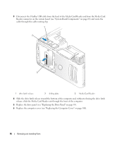
Dell Dimension E520 Owner's Manual - Page 94
Installing a Floppy Drive, located within the drive panel insert or, if applicable
 |
View all Dell Dimension E520 manuals
Add to My Manuals
Save this manual to your list of manuals |
Page 94 highlights
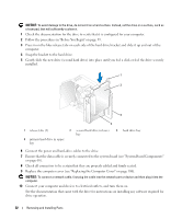
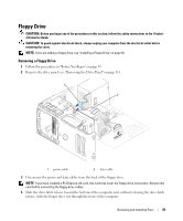
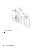
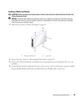
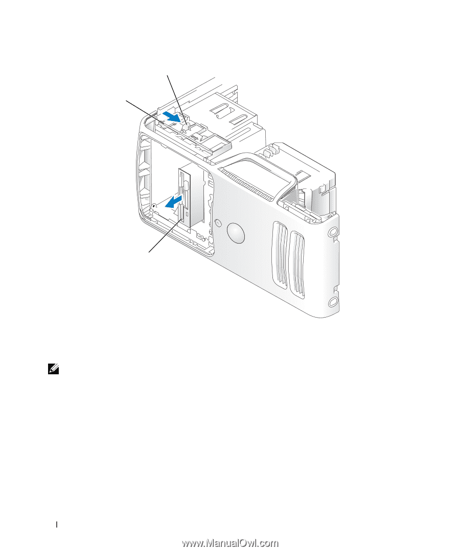
1 2 3 1 drive latch release 2 sliding plate 3 floppy drive Installing a Floppy Drive NOTE: In the event that the replacement or new floppy drive does not have shoulder screws, check for the screws located within the drive panel insert or, if applicable, reuse screws attached to the drive that you are replacing. 94 Removing and Installing Parts
-
 1
1 -
2
-
3
-
4
-
5
-
6
-
7
-
8
-
9
-
10
-
11
-
12
-
13
-
14
-
15
-
16
-
17
-
18
-
19
-
20
-
21
-
22
-
23
-
24
-
25
-
26
-
27
-
28
-
29
-
30
-
31
-
32
-
33
-
34
-
35
-
36
-
37
-
38
-
39
-
40
-
41
-
42
-
43
-
44
-
45
-
46
-
47
-
48
-
49
-
50
-
51
-
52
-
53
-
54
-
55
-
56
-
57
-
58
-
59
-
60
-
61
-
62
-
63
-
64
-
65
-
66
-
67
-
68
-
69
-
70
-
71
-
72
-
73
-
74
-
75
-
76
-
77
-
78
-
79
-
80
-
81
-
82
-
83
-
84
-
85
-
86
-
87
-
88
-
 89
89 -
 90
90 -
 91
91 -
 92
92 -
 93
93 -
 94
94 -
 95
95 -
 96
96 -
 97
97 -
 98
98 -
 99
99 -
100
-
101
-
102
-
103
-
104
-
105
-
106
-
107
-
108
-
109
-
110
-
111
-
112
-
113
-
114
-
115
-
116
-
117
-
118
-
119
-
120
-
121
-
122
-
123
-
124
-
125
-
126
-
127
-
128
-
129
-
130
-
131
-
132
-
133
-
134
-
135
-
136
-
137
-
138
-
139
-
140
-
141
-
142
-
143
-
144
-
145
-
146
-
147
-
148
-
149
-
150
-
151
-
152
-
153
-
154
-
155
-
156
-
157
-
158
-
159
-
160
-
161
-
162
 |
 |
94
Removing and Installing Parts
Installing a Floppy Drive
NOTE:
In the event that the replacement or new floppy drive does not have shoulder screws, check for the screws
located within the drive panel insert or, if applicable, reuse screws attached to the drive that you are replacing.
1
drive latch release
2
sliding plate
3
floppy drive
3
2
1