Dell Dimension E520 Owner's Manual - Page 65
Removing the Computer Cover, Pull back the cover latch release located on the top panel. - video input
 |
View all Dell Dimension E520 manuals
Add to My Manuals
Save this manual to your list of manuals |
Page 65 highlights
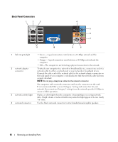
5 line-in connector Use the blue line-in connector to attach a record/playback device such as a cassette player, CD player, or VCR. On computers with a sound card, use the connector on the card. 6 line-out connector Use the green line-out connector (available on computers with integrated sound) to attach headphones and most speakers with integrated amplifiers. On computers with a sound card, use the connector on the card. 7 micro-phone Use the pink connector to attach a personal computer microphone for voice or musical input into a sound or telephony program. On computers with a sound card, the microphone connector is on the card. 8 side surround connector Use the silver connector to provide enhanced surround audio for computers with 7.1 speakers. On computers with a sound card, the microphone connector is on the card. 9 center/subwoofer connector Use the yellow connector to attach a speaker to a Low Frequency Effects (LFE) audio channel. 10 optional VGA video connector If your monitor has a VGA connector, plug it into the VGA connector on the computer. 11 USB 2.0 connectors (6) Use the back USB connectors for devices that typically remain connected, such as printers and keyboards. It is recommended that you use the front USB connectors for devices that you connect occasionally, such as joysticks or cameras. Removing the Computer Cover CAUTION: Before you begin any of the procedures in this section, follow the safety instructions in the Product Information Guide. CAUTION: To guard against electrical shock, always unplug your computer from the electrical outlet before removing the cover. 1 Follow the procedures in "Before You Begin" on page 59. NOTICE: Ensure that sufficient space exists to support the removed cover-at least 30 cm (1 ft) of desk top space. NOTICE: Ensure that you are working on a level, protected surface to avoid scratching either the computer or the surface on which it is resting. 2 Lay your computer on its side with the computer cover facing up. 3 Pull back the cover latch release located on the top panel. Removing and Installing Parts 65
-
 1
1 -
2
-
3
-
4
-
5
-
6
-
7
-
8
-
9
-
10
-
11
-
12
-
13
-
14
-
15
-
16
-
17
-
18
-
19
-
20
-
21
-
22
-
23
-
24
-
25
-
26
-
27
-
28
-
29
-
30
-
31
-
32
-
33
-
34
-
35
-
36
-
37
-
38
-
39
-
40
-
41
-
42
-
43
-
44
-
45
-
46
-
47
-
48
-
49
-
50
-
51
-
52
-
53
-
54
-
55
-
56
-
57
-
58
-
59
-
 60
60 -
 61
61 -
 62
62 -
 63
63 -
 64
64 -
 65
65 -
 66
66 -
 67
67 -
 68
68 -
 69
69 -
 70
70 -
71
-
72
-
73
-
74
-
75
-
76
-
77
-
78
-
79
-
80
-
81
-
82
-
83
-
84
-
85
-
86
-
87
-
88
-
89
-
90
-
91
-
92
-
93
-
94
-
95
-
96
-
97
-
98
-
99
-
100
-
101
-
102
-
103
-
104
-
105
-
106
-
107
-
108
-
109
-
110
-
111
-
112
-
113
-
114
-
115
-
116
-
117
-
118
-
119
-
120
-
121
-
122
-
123
-
124
-
125
-
126
-
127
-
128
-
129
-
130
-
131
-
132
-
133
-
134
-
135
-
136
-
137
-
138
-
139
-
140
-
141
-
142
-
143
-
144
-
145
-
146
-
147
-
148
-
149
-
150
-
151
-
152
-
153
-
154
-
155
-
156
-
157
-
158
-
159
-
160
-
161
-
162
 |
 |