Dell Latitude D630 ATG User's Guide - Page 25
Bottom View
 |
View all Dell Latitude D630 ATG manuals
Add to My Manuals
Save this manual to your list of manuals |
Page 25 highlights
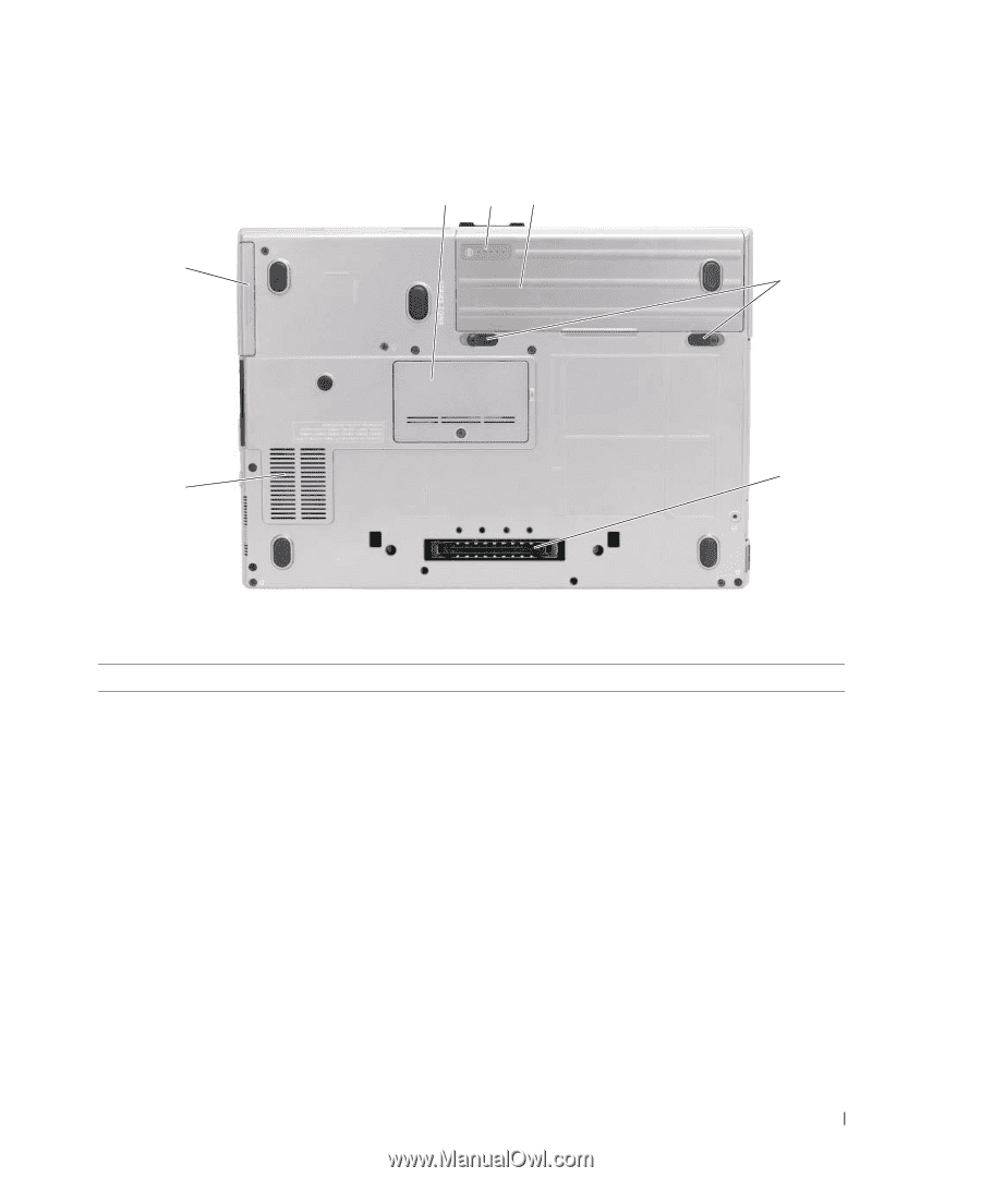
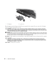
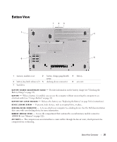
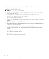
Bottom View 1 23 7 4 6 5 1 memory module cover 2 battery charge gauge/health 3 battery gauge 4 battery-bay latch releases (2) 5 docking-device connector 6 air vents 7 hard drive B A T T E R Y C H A R G E G A U G E / H E A L T H G A U G E - Provides information on the battery charge (see "Checking the Battery Charge" on page 32). B A T T E R Y - When a battery is installed, you can use the computer without connecting the computer to an electrical outlet (see "Using a Battery" on page 31). B A T T E R Y - B A Y L A T C H R EL E A S E S - Releases the battery (see "Replacing the Battery" on page 36 for instructions). D E V I C E L O C K I N G S C R E W - If present, locks devices, such as an optical drive, in place. D O C K I N G - D E V I C E C O N NE C T O R - Lets you attach your computer to a docking device. See the Dell documentation that came with your docking device for more information. M E MO RY M O D U L E C O VE R - Covers the compartment that contains the second memory module connector (DIMM B) (see "Memory" on page 122). AIR V E N T S - The computer uses an internal fan to create airflow through the fan air vents, which prevents the computer from overheating. About Your Computer 25
-
 1
1 -
2
-
3
-
4
-
5
-
6
-
7
-
8
-
9
-
10
-
11
-
12
-
13
-
14
-
15
-
16
-
17
-
18
-
19
-
 20
20 -
 21
21 -
 22
22 -
 23
23 -
 24
24 -
 25
25 -
 26
26 -
 27
27 -
 28
28 -
 29
29 -
 30
30 -
31
-
32
-
33
-
34
-
35
-
36
-
37
-
38
-
39
-
40
-
41
-
42
-
43
-
44
-
45
-
46
-
47
-
48
-
49
-
50
-
51
-
52
-
53
-
54
-
55
-
56
-
57
-
58
-
59
-
60
-
61
-
62
-
63
-
64
-
65
-
66
-
67
-
68
-
69
-
70
-
71
-
72
-
73
-
74
-
75
-
76
-
77
-
78
-
79
-
80
-
81
-
82
-
83
-
84
-
85
-
86
-
87
-
88
-
89
-
90
-
91
-
92
-
93
-
94
-
95
-
96
-
97
-
98
-
99
-
100
-
101
-
102
-
103
-
104
-
105
-
106
-
107
-
108
-
109
-
110
-
111
-
112
-
113
-
114
-
115
-
116
-
117
-
118
-
119
-
120
-
121
-
122
-
123
-
124
-
125
-
126
-
127
-
128
-
129
-
130
-
131
-
132
-
133
-
134
-
135
-
136
-
137
-
138
-
139
-
140
-
141
-
142
-
143
-
144
-
145
-
146
-
147
-
148
-
149
-
150
-
151
-
152
-
153
-
154
-
155
-
156
-
157
-
158
-
159
-
160
-
161
-
162
-
163
-
164
-
165
-
166
 |
 |