Dell PowerEdge 2300 Installation and Troubleshooting Guide
Dell PowerEdge 2300 Manual
 |
View all Dell PowerEdge 2300 manuals
Add to My Manuals
Save this manual to your list of manuals |
Dell PowerEdge 2300 manual content summary:
- Dell PowerEdge 2300 | Installation and Troubleshooting Guide - Page 1
® - Dell PowerEdge 2300 | Installation and Troubleshooting Guide - Page 2
Corporation is strictly forbidden. Trademarks used in this text: Dell, the DELL logo, Dell Dimension, and PowerEdge are registered trademarks and DellWare is a registered service mark of Dell Computer Corporation; Microsoft, MS-DOS, and Windows NT are registered trademarks of Microsoft Corporation - Dell PowerEdge 2300 | Installation and Troubleshooting Guide - Page 3
grounded plugs. To help protect your computer system from sudden, transient increases and decreases in electrical power, use a surge suppressor, line conditioner, or uninterruptible power supply (UPS). Be sure nothing rests on your computer system's cables and that the cables are not located - Dell PowerEdge 2300 | Installation and Troubleshooting Guide - Page 4
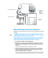
setting up and using your computer system: Position your system so that the monitor and keyboard are directly in front of you as you work. Special shelves are available (from Dell provides good lower back support. Keep your forearms When sitting, make sure the weight of your legs is on your - Dell PowerEdge 2300 | Installation and Troubleshooting Guide - Page 5
at or below eye level arms at desk level monitor and keyboard positioned directly in front of user feet flat on the floor Before you remove the computer covers, perform the following steps in the sequence indicated. Doing so reduces the potential for personal injury or shock. While you work - Dell PowerEdge 2300 | Installation and Troubleshooting Guide - Page 6
an unpainted metal surface on the computer chassis. As you continue to work inside the computer, periodically touch an unpainted metal surface to remove any static charge your body may have accumulated. You can also take the following steps to prevent damage from electrostatic discharge (ESD): When - Dell PowerEdge 2300 | Installation and Troubleshooting Guide - Page 7
is intended for anyone who wants to upgrade or troubleshoot their Dell PowerEdge 2300 computer system. Before calling Dell for technical assistance, follow the recommended procedure(s) in this guide to solve most hardware and software problems yourself. The chapters and appendixes are summarized - Dell PowerEdge 2300 | Installation and Troubleshooting Guide - Page 8
this Installation and Troubleshooting Guide, the following documentation is included with your system: The Dell PowerEdge 2300 Systems User's Guide, which describes system features and technical specifications, video and SCSI device drivers, the System Setup program, software support utilities, and - Dell PowerEdge 2300 | Installation and Troubleshooting Guide - Page 9
in this document. Throughout this guide, there may be blocks of of your computer system. The following list defines (where appropriate) specific elements of text and New font are part of an instruction and intended to be typed. Example: "Type format a: to format the diskette in drive A." Filenames - Dell PowerEdge 2300 | Installation and Troubleshooting Guide - Page 10
.doc Screen text is text that appears on the screen of your monitor or display. It can be a system message, for example, or it can be text that you are instructed to type as part of a command (referred to as a command line). Screen text is presented in the Courier New font. Example: The - Dell PowerEdge 2300 | Installation and Troubleshooting Guide - Page 11
Look and Listen 2-5 The System Setup Program 2-7 The Resource Configuration Utility 2-7 System Messages 3-1 System Beep Codes 3-9 Warning Messages 3-12 Diagnostics Messages 3-12 Alert Log Messages From the Dell HIP Application 3-12 SCSI Hard-Disk Drive Indicator Codes 3-15 Installing and - Dell PowerEdge 2300 | Installation and Troubleshooting Guide - Page 12
Limits 5-10 About 5-10 Key-Help 5-10 Quit 5-10 Tests in the Dell Diagnostics 5-10 Error Messages 5-12 RAM Test Group 5-13 Subtests 5-13 Why Run a RAM Test 5-13 System Set Test Group 5-14 Subtests 5-14 Why Run a System Set Test 5-15 Video Test Group 5-16 Subtests 5-16 Why Run a Video - Dell PowerEdge 2300 | Installation and Troubleshooting Guide - Page 13
Responding to a Dell HIP Alert Message 7-6 Troubleshooting a Wet Computer 7-6 Troubleshooting a Damaged Computer 7-7 Troubleshooting the Battery 7-8 Troubleshooting a Cooling Fan 7-9 Troubleshooting Expansion Cards 7-10 Troubleshooting System Memory 7-12 Troubleshooting the Video Subsystem - Dell PowerEdge 2300 | Installation and Troubleshooting Guide - Page 14
7-15 Troubleshooting the Diskette Drive Subsystem 7-17 Troubleshooting a SCSI Tape Drive 7-20 Troubleshooting SCSI Hard-Disk Drives 7-23 Expansion Cards 8-2 Choosing an Expansion Slot 8-3 Installing an Expansion Card 8-4 Removing an Expansion Card 8-5 Adding Memory 8-6 Memory Upgrade Kits - Dell PowerEdge 2300 | Installation and Troubleshooting Guide - Page 15
Installing and Removing SCSI Hard-Disk Drives 10-4 Hot-Pluggable SCSI Hard-Disk Drives 10-4 Indicator Codes for Hot-Pluggable SCSI Hard-Disk Drives 10-4 Installing a SCSI Hard-Disk Drive 10-6 Removing a SCSI Hard-Disk Drive 10-7 Installing a Dell PowerEdge Expandable RAID Controller Host - Dell PowerEdge 2300 | Installation and Troubleshooting Guide - Page 16
System Board Labels B-5 Hot-Pluggable SCSI Backplane Board B-6 Non-Hot-Pluggable SCSI Backplane Boards B-7 Disabling a Forgotten Password B-8 Figure 2-1. Figure 2-2. Figure 3-1. Figure 5-1. Figure 5-2. Figure 7-1. Back Panel Features 2-3 Front Panel Features 2-4 Hard-Disk Drive Indicators - Dell PowerEdge 2300 | Installation and Troubleshooting Guide - Page 17
Drive Hardware (1 x 6 Hot-Pluggable SCSI Backplane Board Shown 10-2 Figure 10-2. SCSI Backplane Boards 10-3 Figure 10-3. Hard-DIsk Drive Indicators 10-5 Figure 10-4. Installing a SCSI Hard-Disk Drive Carrier 10-6 Figure 10-5. Cable Configuration for a Dell PowerEdge Expandable RAID Controller - Dell PowerEdge 2300 | Installation and Troubleshooting Guide - Page 18
Characteristics 10-1 SCSI Hard-Disk Drive Indicator Patterns 10-5 Help Tools 11-2 International Dialing Codes 11-11 Dell Contact Numbers 11-12 Color Attributes A-4 System-Board Jumper Settings B-4 System Board Connectors and Sockets B-5 1 x 6 Hot-Pluggable SCSI Backplane Board Connectors - Dell PowerEdge 2300 | Installation and Troubleshooting Guide - Page 19
system cooling fan malfunctions. The Dell PowerEdge 2300 system chassis simplifies removing and replacing computer components. You can perform processor and memory upgrades without removing the system board. The Dell-designed small computer system interface (SCSI) backplane board and hard-disk drive - Dell PowerEdge 2300 | Installation and Troubleshooting Guide - Page 20
1-2 Dell PowerEdge 2300 Systems Installation and Troubleshooting Guide - Dell PowerEdge 2300 | Installation and Troubleshooting Guide - Page 21
Dell PowerEdge 2300 computer system is not working as expected, start your troubleshooting with the procedures in this chapter. This chapter guides you through some initial checks and procedures that can solve basic computer problems. It can also direct you to the appropriate chapter in this guide - Dell PowerEdge 2300 | Installation and Troubleshooting Guide - Page 22
. Go to Chapter 11, "Getting Help." Yes. Go to Chapter 3, "Messages and Codes." No. Go to step 6. Is the problem resolved? Yes. The system configuration information was incorrect. You have fixed the problem. No. Go to step 7. 2-2 Dell PowerEdge 2300 Systems Installation and Troubleshooting Guide - Dell PowerEdge 2300 | Installation and Troubleshooting Guide - Page 23
2-1 shows the back panel connections on the computer. Figure 2-2 shows the switches and controls on the computer. AC power receptacle SCSI connector ports (2) mouse connector keyboard connector server management bus (SMB) connectors (2) serial port 1 connector parallel port connector serial port - Dell PowerEdge 2300 | Installation and Troubleshooting Guide - Page 24
: Is the power strip receiving power? Yes. Go to step 5. No. Go to step 3. Is the power strip receiving power? Yes. The original electrical outlet probably does not function. Use a different electrical outlet. No. Go to step 4. 2-4 Dell PowerEdge 2300 Systems Installation and Troubleshooting Guide - Dell PowerEdge 2300 | Installation and Troubleshooting Guide - Page 25
6. Yes. Continue with "Look and Listen" found next in this chapter. No. Go to "Troubleshooting I/O Ports" in Chapter 6. Looking at and listening to the system is important in determining the source of a problem. Look and listen for the indications described in Table 2-1. Checking the Basics 2-5 - Dell PowerEdge 2300 | Installation and Troubleshooting Guide - Page 26
access data on the hard-disk drives. On a system running the Microsoft® Windows NT® operating system, you can test the drive by opening Windows Explorer and clicking the icon for drive C. If the hard-disk drive access indicator does not come on, see "Troubleshooting SCSI Hard-Disk Drives" in Chapter - Dell PowerEdge 2300 | Installation and Troubleshooting Guide - Page 27
program, correct the corresponding System Setup setting, and reboot the system. See Chapter 4, "Using the System Setup Program," in the Dell PowerEdge 2300 Systems User's Guide for detailed instructions on using the System Setup program. If you are experiencing problems with the system, you may have - Dell PowerEdge 2300 | Installation and Troubleshooting Guide - Page 28
2-8 Dell PowerEdge 2300 Systems Installation and Troubleshooting Guide - Dell PowerEdge 2300 | Installation and Troubleshooting Guide - Page 29
. Several different types of messages can indicate when the system is not functioning properly: System messages System beep codes Warning messages Diagnostics messages Alert messages Small computer system interface (SCSI) hard-disk drive indicator codes This chapter describes each type of message - Dell PowerEdge 2300 | Installation and Troubleshooting Guide - Page 30
settings in System Setup program, loose diskette/ tape drive interface cable, or loose power cable Replace the diskette. Run the System Setup program to correct the diskette drive type. See Chapter 4, "Using the System Setup Program," in the Dell PowerEdge 2300 Systems User's Guide for instructions - Dell PowerEdge 2300 | Installation and Troubleshooting Guide - Page 31
server management memory may be temporarily corrupted Shut down the system to clear the memory, and then restart the system. If the problem persists, see Chapter 11, "Getting Help," for instructions on obtaining technical assistance. Gate A20 failure Faulty keyboard controller (defective system - Dell PowerEdge 2300 | Installation and Troubleshooting Guide - Page 32
hard-disk drive, faulty hard-disk drive controller subsystem (defective system board), or loose power cable Check the hard-disk drive configuration settings in the System Setup program. See Chapter 4, "Using the System Setup Program," in the Dell PowerEdge 2300 Systems User's Guide for instructions - Dell PowerEdge 2300 | Installation and Troubleshooting Guide - Page 33
keyboard. If the problem persists, replace the system board. See Chapter 11, "Getting Help," for instructions on obtaining technical assistance. Remove and reseat the DIMMs. If the problem persists, replace the DIMMs. See "Installing DIMMs" and "Removing DIMMs" in Chapter 8. Memory odd/even logic - Dell PowerEdge 2300 | Installation and Troubleshooting Guide - Page 34
drive Incorrect configuration settings in System Setup program, or no operating system on hard-disk drive Check the hard-disk drive configuration settings in the System Setup program. See Chapter 4, "Using the System Setup Program," in the Dell PowerEdge 2300 Systems User's Guide for instructions - Dell PowerEdge 2300 | Installation and Troubleshooting Guide - Page 35
found Faulty diskette, diskette/ tape drive subsystem, or hard-disk drive subsystem (defective system board) Replace the diskette or harddisk drive. If the problem persists, replace the system board. See Chapter 11, "Getting Help," for instructions on obtaining technical assistance. Reset failed - Dell PowerEdge 2300 | Installation and Troubleshooting Guide - Page 36
Board Options," for instructions. Unsupported CPU speed in CMOS Microprocessor not supported by BIOS Upgrade the BIOS. See Chapter 2, "Using the System Setup Program," in the Dell PowerEdge 2300 Systems User's Guide for instructions. Write fault Write fault on selected drive Faulty diskette or - Dell PowerEdge 2300 | Installation and Troubleshooting Guide - Page 37
memory (NVRAM). This information is valuable to the Dell technical support system. If the problem persists, replace the system board. See Chapter 11, "Getting Help," for instructions on obtaining technical assistance. 1-3-2 No memory installed Remove and reseat the DIMMs. See "Removing - Dell PowerEdge 2300 | Installation and Troubleshooting Guide - Page 38
. See Chapter 11, "Getting Help," for instructions on obtaining technical assistance. NOTE: For the full name of an abbreviation or acronym used in this table, see the abbreviation and acronym list that precedes the Index. 3-10 Dell PowerEdge 2300 Systems Installation and Troubleshooting Guide - Dell PowerEdge 2300 | Installation and Troubleshooting Guide - Page 39
seated or faulty DIMMs Remove and reseat the DIMMs. See "Removing DIMMs" and "Installing DIMMs" in Chapter 8. If the problem persists, replace the DIMMs. 4-3-3 Defective system board Replace the system board. See Chapter 11, "Getting Help," for instructions on obtaining technical assistance - Dell PowerEdge 2300 | Installation and Troubleshooting Guide - Page 40
NNM SE 1.1 With Dell OpenManage HIP 3.1 User's Guide.) Alert log messages consist of information, status, warning, and failure messages for drive, temperature, fan, and power conditions. They can assist you with identifying a 3-12 Dell PowerEdge 2300 Systems Installation and Troubleshooting Guide - Dell PowerEdge 2300 | Installation and Troubleshooting Guide - Page 41
ECC fault detected An ECC error has occurred in system memory. Run the appropriate memory test(s) from your Dell Diagnostics. See Chapter 5, "Running the Dell Diagnostics," for more information. * Supported for local server action NOTE: For the full name of an abbreviation or acronym used in - Dell PowerEdge 2300 | Installation and Troubleshooting Guide - Page 42
properly, call Dell for technical assistance. * Supported for local server action NOTE: For the full name of an abbreviation or acronym used in this table, see the abbreviations and acronyms list that precedes the Index. 3-14 Dell PowerEdge 2300 Systems Installation and Troubleshooting Guide - Dell PowerEdge 2300 | Installation and Troubleshooting Guide - Page 43
1 x 6 hot-pluggable SCSI backplane board is installed in the system, three lightemitting diode (LED) indicators adjacent to each of the six SCSI hard-disk drive bays provide information on the status of the SCSI hard-disk drives (see Figure 3-1). The SCSI backplane firmware controls the drive online - Dell PowerEdge 2300 | Installation and Troubleshooting Guide - Page 44
. Drive failed The drive online indicator turns off. The drive failure indicator blinks off briefly each second. Drive rebuilding The drive online indicator blinks rapidly. Drive online The drive online indicator is on. 3-16 Dell PowerEdge 2300 Systems Installation and Troubleshooting Guide - Dell PowerEdge 2300 | Installation and Troubleshooting Guide - Page 45
System Set Test Group as described in Chapter 5, "Running the Dell Diagnostics." If all tests in the test group complete successfully, the error condition is most likely caused by software. This chapter provides some general guidelines for analyzing software problems. For detailed troubleshooting - Dell PowerEdge 2300 | Installation and Troubleshooting Guide - Page 46
the computer's hard-disk drive. Installation instructions may provide details about how to configure the operating system to successfully . Call the support service for the software you are using to help you with this problem. 4-2 Dell PowerEdge 2300 Systems Installation and Troubleshooting Guide - Dell PowerEdge 2300 | Installation and Troubleshooting Guide - Page 47
line setting for each installed expansion card. Then consult Table 4-1 to configure the card for one of the available IRQ lines. IRQ0 Used by the system the diskette drive controller IRQ7 Used by the primary parallel port IRQ8 Used by the RTC IRQ9 Used for power management functions IRQ10 - Dell PowerEdge 2300 | Installation and Troubleshooting Guide - Page 48
4-4 Dell PowerEdge 2300 Systems Installation and Troubleshooting Guide - Dell PowerEdge 2300 | Installation and Troubleshooting Guide - Page 49
system's operation. And if you find a problem you cannot solve by yourself, the diagnostic tests can provide you with important information you will need when talking to Dell's technical support representative. The Dell if an error is detected or to terminate testing when an adjustable error limit is - Dell PowerEdge 2300 | Installation and Troubleshooting Guide - Page 50
the scope of the problem, read the rest of this chapter. Follow these steps to run the diagnostics: See "Create Diskettes" in Chapter 2 of the Dell PowerEdge 2300 Systems User's Guide. If the system fails to boot, see Chapter 11, "Getting Help," for instructions on obtaining technical assistance - Dell PowerEdge 2300 | Installation and Troubleshooting Guide - Page 51
Corporation Dell PowerEdge 2300 Diagnostics Version X.XX DIAGNOSTICS Run All Tests RUn Quick Tests RuN Specific Tests Exit When you select Run Specific Tests from the Diagnostics Menu, the main screen of the diagnostics appears. Figure 5-2 shows a sample main screen; the actual text on your system - Dell PowerEdge 2300 | Installation and Troubleshooting Guide - Page 52
Computer Corporation Dell PowerEdge 2300 Diagnostics Version X.XX Available Test Groups System Configuration RAM System Set Video Keyboard Mouse Diskette Drives Serial/Infrared Ports Parallel Ports SCSI Devices Other Processor Pentium II Memory 128 MB Secondary Cache 512 KB I/O APIC Video - Dell PowerEdge 2300 | Installation and Troubleshooting Guide - Page 53
(by selecting Run), you should consider setting global parameters within the Options option. They offer you greater control over how the test groups or subtests The Key-Help option displays a list of key controls available for the particular option you have chosen. The Quit Menu option returns you - Dell PowerEdge 2300 | Installation and Troubleshooting Guide - Page 54
>. Press the up- or down-arrow key to highlight a subtest to be selected. To reverse a subtest selection, highlight the subtest and press the . To clear all selections, select Clear All. 5-6 Dell PowerEdge 2300 Systems Installation and Troubleshooting Guide - Dell PowerEdge 2300 | Installation and Troubleshooting Guide - Page 55
information about the highlighted subtest. The Key-Help option in the Subtest menu displays a list of key controls available. The Quit Menu option in the Subtest menu returns you to the previous menu. . Table and right-arrow keys, or the plus (+) and minus (-) keys. Running the Dell Diagnostics 5-7 - Dell PowerEdge 2300 | Installation and Troubleshooting Guide - Page 56
drive set to No, the diagnostics ignores some subtests that require your interaction; certain subtests can run only if this option is set to Yes because they require user interaction. Use the Pause parameter in situations where 5-8 Dell PowerEdge 2300 Systems Installation and Troubleshooting Guide - Dell PowerEdge 2300 | Installation and Troubleshooting Guide - Page 57
file is automatically created on a diskette in drive A when you run the diagnostics. If so that it is clear for the next set of messages generated. Otherwise is automatically created on a diskette in drive A when you run the diagnostics. that it is clear for the next set of messages generated. - Dell PowerEdge 2300 | Installation and Troubleshooting Guide - Page 58
. The diagnostics exercises the functional components and devices of the computer system more vigorously and thoroughly than they are exercised during normal operation. The diagnostics is organized by components into test 5-10 Dell PowerEdge 2300 Systems Installation and Troubleshooting Guide - Dell PowerEdge 2300 | Installation and Troubleshooting Guide - Page 59
use. RAM System Set Quick Memory Test Comprehensive Memory Test Cache Memory Test CMOS Confidence Test DMA Controller Test Real-Time Clock Test System Timers Test Interrupt Controller Test APIC Test APIC MP Test System Speaker Test Tests the system RAM and processor cache. Tests the system board - Dell PowerEdge 2300 | Installation and Troubleshooting Guide - Page 60
messages on a copy of the Diagnostics Checklist found in Chapter 11, "Getting Help;" also see Chapter 11 for instructions on obtaining technical assistance and informing the technical support representative of these messages. 5-12 Dell PowerEdge 2300 Systems Installation and Troubleshooting Guide - Dell PowerEdge 2300 | Installation and Troubleshooting Guide - Page 61
, to verify that the dynamic RAM (DRAM) is being recharged properly The Cache Memory Test confirms the functionality of the computer's cache controller chip and the cache memory. Faulty memory can cause a variety of problems that may not appear to be happening in RAM. If the computer is displaying - Dell PowerEdge 2300 | Installation and Troubleshooting Guide - Page 62
APIC. System Speaker Test Checks the functionality of the speaker by generating eight tones. Coprocessor Calculation Test Checks the use of different types of numbers and the math coprocessor's ability to calculate correctly. 5-14 Dell PowerEdge 2300 Systems Installation and Troubleshooting Guide - Dell PowerEdge 2300 | Installation and Troubleshooting Guide - Page 63
microprocessor is operational. The System Set subtests double-check many system board components, such as the computer's I/O circuitry, that are tested by other test groups or subtests in the diagnostics. You should run the System Set Test Group if you are having a problem and cannot isolate the - Dell PowerEdge 2300 | Installation and Troubleshooting Guide - Page 64
and the controller. They write, read, and verify data patterns in the cursor registers of the controller. The Video Test Group also tests all the video memory and provides additional you to check for missing color subpixels. 5-16 Dell PowerEdge 2300 Systems Installation and Troubleshooting Guide - Dell PowerEdge 2300 | Installation and Troubleshooting Guide - Page 65
run the Video Test Group or any of its subtests, you should make sure that the problem is not in the software or caused by a hardware change. You should also try running all of the software support utilities provided for the monitor and the video subsystem. If the following symptoms still occur - Dell PowerEdge 2300 | Installation and Troubleshooting Guide - Page 66
of the mouse controller (which coordinates cursor movement on the screen with corresponding movement of the mouse or touch pad) and the operation of the mouse keys/touch pad. There are no subtests for the Mouse Test Group. 5-18 Dell PowerEdge 2300 Systems Installation and Troubleshooting Guide - Dell PowerEdge 2300 | Installation and Troubleshooting Guide - Page 67
RAM-related problems include the configuration of a program (which changes the function of the mouse or touch pad), memory-resident programs, and failure of a device driver (the software that controls diskette drive controller and for defective lines on the diskette cable Seek Test Checks the drive's - Dell PowerEdge 2300 | Installation and Troubleshooting Guide - Page 68
symptoms usually suggest a drive problem and warrant running a subtest in the Diskette Drives Test Group: An error the subtests in the Serial/Infrared Ports Test Group fails, remove the modem and run the diagnostic tests again. If an Dell PowerEdge 2300 Systems Installation and Troubleshooting Guide - Dell PowerEdge 2300 | Installation and Troubleshooting Guide - Page 69
the Serial/Infrared Port option to see whether the port has been disabled. (See Chapter 4, "Using the System Setup Program," in the Dell PowerEdge 2300 Systems User's Guide for instructions.) The subtests in the Serial/Infrared Ports Test Group cannot test a port unless it is enabled. When a port - Dell PowerEdge 2300 | Installation and Troubleshooting Guide - Page 70
system configuration information settings, peripheral malfunctions, and software errors as potential causes of port problems, you can run the subtests in the Parallel Ports Test Group to check the hardware. Although the 5-22 Dell PowerEdge 2300 Systems Installation and Troubleshooting Guide - Dell PowerEdge 2300 | Installation and Troubleshooting Guide - Page 71
setting in the System Setup program and, if necessary, run the appropriate subtest in the Parallel Ports Test Group. The subtests in the SCSI The Audio Output Test requires a CD with audio tracks. If a CD-ROM drive is empty or if it contains a CD that does not have the required Dell Diagnostics 5-23 - Dell PowerEdge 2300 | Installation and Troubleshooting Guide - Page 72
taken if a problem is detected. The three subtests in the Other Test Group and the functions they test follow: ESM Firmware Status Tests to make sure the ESM software was downloaded correctly and that the system is operational. 5-24 Dell PowerEdge 2300 Systems Installation and Troubleshooting Guide - Dell PowerEdge 2300 | Installation and Troubleshooting Guide - Page 73
. These are the most common symptoms that might prompt you to run the ESM subtests in the Other Test Group: If the Dell HIP server management application returns a warning dealing with server management If you want to verify that all voltages in the system are being reported properly Running the - Dell PowerEdge 2300 | Installation and Troubleshooting Guide - Page 74
5-26 Dell PowerEdge 2300 Systems Installation and Troubleshooting Guide - Dell PowerEdge 2300 | Installation and Troubleshooting Guide - Page 75
in this chapter: The Dell Server Assistant CD A blank, formatted diskette The system documentation NOTE: When you see the question, "Is the problem resolved?" in a troubleshooting procedure, perform the operation that caused the problem. Troubleshooting video problems involves determining which of - Dell PowerEdge 2300 | Installation and Troubleshooting Guide - Page 76
computer, see "Troubleshooting Expansion Cards" in Chapter 7. If no video expansion card is installed, the built-in video controller is faulty; see Chapter 11, "Getting Help," for instructions on obtaining technical assistance. 6-2 Dell PowerEdge 2300 Systems Installation and Troubleshooting Guide - Dell PowerEdge 2300 | Installation and Troubleshooting Guide - Page 77
back panel and plug in a working keyboard. Is the problem resolved? Yes. The keyboard must be replaced. See Chapter 11, "Getting Help," for instructions on obtaining technical assistance. No. Go to step 3. See Chapter 5, "Running the Dell Diagnostics." Can you use the keyboard to select the Keyboard - Dell PowerEdge 2300 | Installation and Troubleshooting Guide - Page 78
not function properly, follow these steps: Are the communications ports set to Auto, and is Mouse set to Enabled? Yes. Go to step 3. No. Go to step 2. Is the problem resolved? Yes. You have fixed the problem. No. Go to step 3. 6-4 Dell PowerEdge 2300 Systems Installation and Troubleshooting Guide - Dell PowerEdge 2300 | Installation and Troubleshooting Guide - Page 79
? Yes. Go to step 6. No. See Chapter 11, "Getting Help," for instructions on obtaining technical assistance. If the procedure in the preceding subsection, "Troubleshooting the Basic I/O Functions," indicates that the problem is with a parallel printer, follow these steps: Checking the Equipment 6-5 - Dell PowerEdge 2300 | Installation and Troubleshooting Guide - Page 80
connected to the computer? Yes. Go to step 2. No. Go to step 4. Is the problem resolved? Yes. The serial port may be defective. See Chapter 11, "Getting Help," for instructions on obtaining technical assistance. No. Go to step 4. 6-6 Dell PowerEdge 2300 Systems Installation and Troubleshooting Guide - Dell PowerEdge 2300 | Installation and Troubleshooting Guide - Page 81
must be replaced. See Chapter 11, "Getting Help," for instructions on obtaining technical assistance. No. Go to step 5. For example, if the serial mouse has a problem, swap it with a serial mouse that you know is working properly. Is the problem resolved? Yes. The serial device must be replaced. See - Dell PowerEdge 2300 | Installation and Troubleshooting Guide - Page 82
6-8 Dell PowerEdge 2300 Systems Installation and Troubleshooting Guide - Dell PowerEdge 2300 | Installation and Troubleshooting Guide - Page 83
3.5-inch diskette The Dell PowerEdge 2300 Systems User's Guide The key to the system keylock NOTE: When you see the question, "Is the problem resolved?" in a troubleshooting procedure, perform the operation that caused the problem. The procedures in this guide require that you remove the covers and - Dell PowerEdge 2300 | Installation and Troubleshooting Guide - Page 84
bezel. Removal of the right-side computer cover allows access to the system board, SCSI backplane board, and external SCSI devices. Removal of the left-side computer cover permits access to the diskette-drive interface cable. 7-2 Dell PowerEdge 2300 Systems Installation and Troubleshooting Guide - Dell PowerEdge 2300 | Installation and Troubleshooting Guide - Page 85
Use the following procedure to remove the computer covers: front bezel Checking Inside the Computer 7-3 - Dell PowerEdge 2300 | Installation and Troubleshooting Guide - Page 86
thumbscrews (6) side covers (2) Use the following procedure to replace a computer cover: 7-4 Dell PowerEdge 2300 Systems Installation and Troubleshooting Guide - Dell PowerEdge 2300 | Installation and Troubleshooting Guide - Page 87
, see Chapter 9, "Installing Drives in the External Bays" and Chapter 10, "Installing Hard-Disk Drives.") During an installation or troubleshooting procedure, you may be required to change a jumper or switch setting. For information on the system board jumpers, see Appendix B, "Jumpers and Switches - Dell PowerEdge 2300 | Installation and Troubleshooting Guide - Page 88
bays (4) hard-disk drive bays(4-6) DC power cable interface cable SCSI backplane board system board The Dell Hardware Instrumentation Package (HIP) server management application monitors critical system voltages and temperatures, the system cooling fans, and the status of the SCSI hard-disk drives - Dell PowerEdge 2300 | Installation and Troubleshooting Guide - Page 89
See "Removing an Expansion Card" in Chapter 8. Does the system have power? Yes. Go to step 6. No. See Chapter 11, "Getting Help," for instructions on instructions or see Chapter 11, "Getting Help," for information on obtaining technical assistance from Dell. Follow these steps to troubleshoot - Dell PowerEdge 2300 | Installation and Troubleshooting Guide - Page 90
problem with the battery, or if the System Setup program loses the system configuration information when the computer is turned off, the battery may be defective. Follow these steps to troubleshoot the battery: See "Removing the Computer Covers" found earlier in this chapter. 7-8 Dell PowerEdge 2300 - Dell PowerEdge 2300 | Installation and Troubleshooting Guide - Page 91
PowerEdge 2300 system chassis. If you observe that one of the cooling fans is not operating, if the cooling fan in the power supply bay is not operating, or if the Dell HIP server-management application issues a fan-related error message, follow these steps to troubleshoot the problem: See "Removing - Dell PowerEdge 2300 | Installation and Troubleshooting Guide - Page 92
problem could be a faulty connection, a conflict with software or other hardware, or a faulty expansion card. Follow these steps to troubleshoot expansion cards: See Chapter 5, "Using the Resource Configuration Utility," in the Dell PowerEdge 2300 Systems User's Guide for instructions. See "Removing - Dell PowerEdge 2300 | Installation and Troubleshooting Guide - Page 93
memory configuration of the card was incorrect. You have fixed the problem. No. Go to step 10. See "Removing an Expansion Card" in Chapter 8 for information on removing expansion cards. See Chapter 4, "Using the System Setup Program," in the Dell PowerEdge 2300 Systems User's Guide for instructions - Dell PowerEdge 2300 | Installation and Troubleshooting Guide - Page 94
the System Setup program is set to On, the Num Lock indicator should flash momentarily and then remain on; otherwise, it should turn off. Abnormal operation of these indicators can result from a defective DIMM in socket DIMM_A. 7-12 Dell PowerEdge 2300 Systems Installation and Troubleshooting Guide - Dell PowerEdge 2300 | Installation and Troubleshooting Guide - Page 95
to step 8. See Chapter 4, "Using the System Setup Program," in the Dell PowerEdge 2300 Systems User's Guide for instructions. Does the amount of memory installed match the Total Memory or System Memory setting? Yes. Go to step 8. No. Go to step 3. See "Removing the Computer Covers" found earlier in - Dell PowerEdge 2300 | Installation and Troubleshooting Guide - Page 96
of the problem. If you have a high-resolution video expansion card, first complete the steps in "Troubleshooting Expansion Cards" found earlier in this chapter to verify that the card is configured and installed correctly. 7-14 Dell PowerEdge 2300 Systems Installation and Troubleshooting Guide - Dell PowerEdge 2300 | Installation and Troubleshooting Guide - Page 97
for instructions on obtaining technical assistance. A system board problem can result from a defective system board component, a faulty power supply, or a defective component connected to the system board. If an error message indicates a system board problem, follow these steps to troubleshoot the - Dell PowerEdge 2300 | Installation and Troubleshooting Guide - Page 98
Systems User's Guide for instructions. See Chapter 5, "Running the Dell Diagnostics." Do the tests complete successfully? Yes. Go to step 8. No. Go to step 13. Do the tests complete successfully? Yes. Go to step 12. No. Go to step 13. 7-16 Dell PowerEdge 2300 Systems Installation and Troubleshooting - Dell PowerEdge 2300 | Installation and Troubleshooting Guide - Page 99
for instructions on obtaining technical assistance. If the monitor displays a system error message indicating a diskette drive problem during execution of either the boot routine or the Dell Diagnostics, the problem may be caused by any of the following conditions: The system configuration settings - Dell PowerEdge 2300 | Installation and Troubleshooting Guide - Page 100
the diskette drive interface cable connector securely connected to the interface connector (labeled "FLOPPY") on the system board? Is the drive's DC power cable firmly connected to the drive? Yes. Go to step 8. No. Go to step 7. 7-18 Dell PowerEdge 2300 Systems Installation and Troubleshooting Guide - Dell PowerEdge 2300 | Installation and Troubleshooting Guide - Page 101
the Dell Diagnostics," for more information. Do the tests complete successfully? Yes. You have fixed the problem. No. Go to step 10. See "Removing an Expansion Card" in Chapter 8 for instructions. Do the tests complete successfully? Yes. An expansion card may be conflicting with the diskette drive - Dell PowerEdge 2300 | Installation and Troubleshooting Guide - Page 102
card installed in the computer, which may also control other SCSI devices connected to one or more SCSI cables. SCSI devices often require device drivers for the particular operating system being used by the computer system. 7-20 Dell PowerEdge 2300 Systems Installation and Troubleshooting Guide - Dell PowerEdge 2300 | Installation and Troubleshooting Guide - Page 103
See Chapter 3, "Installing and Configuring SCSI Drivers," in the Dell PowerEdge 2300 Systems User's Guide for instructions on installing and configuring the SCSI device drivers for the system's on-board SCSI host adapter or Dell PowerEdge Expandable RAID Controller host adapter card. For any other - Dell PowerEdge 2300 | Installation and Troubleshooting Guide - Page 104
or disabling termination. Is the tape drive configured correctly? Yes. Go to step 14. No. Go to step 12. Is the problem resolved? Yes. The tape drive was configured incorrectly. You have fixed the problem. No. Go to step 13. 7-22 Dell PowerEdge 2300 Systems Installation and Troubleshooting Guide - Dell PowerEdge 2300 | Installation and Troubleshooting Guide - Page 105
to the backplane board. In the event of a drive failure, systems using the optional Dell PowerEdge Expandable RAID Controller host adapter card will issue the following signals using the drive indicator lights adjacent to each SCSI hard-disk drive: If a drive shows signs of imminent failure, the - Dell PowerEdge 2300 | Installation and Troubleshooting Guide - Page 106
expansion slot. See Chapter 10, "Installing Hard-Disk Drives," for the location of the cable connectors on the SCSI backplane board and the SCSI host adapter. Are the cables firmly connected? Yes. Go to step 9. No. Go to step 8. 7-24 Dell PowerEdge 2300 Systems Installation and Troubleshooting Guide - Dell PowerEdge 2300 | Installation and Troubleshooting Guide - Page 107
To partition and logically format the drive, see the documentation for the computer's operating system. Is the problem resolved? Yes. The hard-disk drive format was corrupted. You have fixed the problem. No. See Chapter 11, "Getting Help," for instructions on obtaining technical assistance. Checking - Dell PowerEdge 2300 | Installation and Troubleshooting Guide - Page 108
7-26 Dell PowerEdge 2300 Systems Installation and Troubleshooting Guide - Dell PowerEdge 2300 | Installation and Troubleshooting Guide - Page 109
(ISA) and Peripheral Component Interconnect (PCI) expansion cards Memory upgrades Microprocessor upgrades This chapter also includes instructions for replacing the system battery, if necessary. Use Figure 8-1 to locate the system board features mentioned in this chapter and elsewhere. Installing - Dell PowerEdge 2300 | Installation and Troubleshooting Guide - Page 110
/Narrow SCSI connector (SCSI2) Ultra2/LVD SCSI connector (SCSI1) fan connectors (FAN1, FAN2) hard-disk drive activity indicator connector (HLED) secondary microprocessor (PROCESSOR 2) Dell Remote Assistant Card connector (SVR_MGT) front of system board speed and configuration jumpers power input - Dell PowerEdge 2300 | Installation and Troubleshooting Guide - Page 111
six expansion cards can be installed. Connectors PCI1 through PCI6 support 32-bit PCI cards (see Figure 8-3). Connectors ISA5 and ISA6 support 8- and 16-bit ISA cards. Follow these guidelines and ISA6. PCI slots PCI1 and PCI2 support half-length expansion cards. Installing System Board Options 8-3 - Dell PowerEdge 2300 | Installation and Troubleshooting Guide - Page 112
. See "Removing the Computer Covers" in Chapter 7. See the documentation that came with the expansion card for information on configuring the card, making internal connections, or otherwise customizing the card for the system. 8-4 Dell PowerEdge 2300 Systems Installation and Troubleshooting Guide - Dell PowerEdge 2300 | Installation and Troubleshooting Guide - Page 113
any required PCI configuration tasks during the boot routine. Follow this procedure to remove an expansion card: See Chapter 5, "Using the Resource Configuration Utility," in the Dell PowerEdge 2300 Systems User's Guide for instructions. See "Removing the Computer Covers" in Chapter 7. Installing - Dell PowerEdge 2300 | Installation and Troubleshooting Guide - Page 114
Utility," in the Dell PowerEdge 2300 Systems User's Guide for instructions. NOTE: If you removed a PCI expansion card, the system automatically performs any required re-configuration tasks during the boot routine. The four dual in-line memory module (DIMM) sockets on the system board can accommodate - Dell PowerEdge 2300 | Installation and Troubleshooting Guide - Page 115
be mixed. If you install 256-MB registered DIMMs, you must remove any 64- or 128-MB unbuffered DIMMs from the computer. DIMMs need not be installed in pairs. DIMM_D DIMM_A back of system board Table 8-1 illustrates several sample memory configurations based on these guidelines. 64 MB 128 MB 128 - Dell PowerEdge 2300 | Installation and Troubleshooting Guide - Page 116
the Base Memory and Extended Memory values. If the total is incorrect, one or more of the DIMMs may not be installed properly. Repeat this procedure again, checking to make sure the DIMMs are firmly seated in their sockets. 8-8 Dell PowerEdge 2300 Systems Installation and Troubleshooting Guide - Dell PowerEdge 2300 | Installation and Troubleshooting Guide - Page 117
DIMM(s). See Chapter 5, "Using the Resource Configuration Utility," in the Dell PowerEdge 2300 Systems User's Guide for instructions on running the utility and saving the configuration. See Chapter 5, "Running the Dell Diagnostics," for information. Install DIMMs starting with socket DIMM_A, located - Dell PowerEdge 2300 | Installation and Troubleshooting Guide - Page 118
remove system has only one microprocessor, the secondary guide bracket assembly connector must contain a terminator system has a 350-MHz primary microprocessor, your secondary microprocessor must also be a 350-MHz microprocessor. 8-10 Dell PowerEdge 2300 Systems Installation and Troubleshooting Guide - Dell PowerEdge 2300 | Installation and Troubleshooting Guide - Page 119
illustrated in Figure 8-7, to remove a terminator card from a guide bracket assembly: Using the thumb and forefinger of each hand, pinch the vertical tabs at each end of the retaining clip and lift the clip straight up. retaining clip terminator card guide bracket assembly socket tabs (2) notch - Dell PowerEdge 2300 | Installation and Troubleshooting Guide - Page 120
Use the following procedure to remove the SEC cartridge and heat sink assembly. release latches (2) Moderate force may be required to disengage the SEC cartridge from the guide bracket assembly connector. 8-12 Dell PowerEdge 2300 Systems Installation and Troubleshooting Guide - Dell PowerEdge 2300 | Installation and Troubleshooting Guide - Page 121
SEC cartridge SEC cartridge release latches (2) heat sink guide bracket assembly Use the following procedure to install the replacement SEC cartridge and heat sink assembly: Follow the instructions in "Removing a Terminator Card" or "Removing the SEC Cartridge and Heat Sink Assembly" found earlier - Dell PowerEdge 2300 | Installation and Troubleshooting Guide - Page 122
or System CMOS checksum bad - Run SETUP Strike the F1 key to continue, F2 to run the setup utility or Invalid configuration information - please run SETUP program Strike the F1 key to continue, F2 to run the setup utility 8-14 Dell PowerEdge 2300 Systems Installation and Troubleshooting Guide - Dell PowerEdge 2300 | Installation and Troubleshooting Guide - Page 123
. The battery is a 3.0-volt (V), coin-cell CR2032-type battery. To remove the battery, follow these steps. See Chapter 4, "Using the System Setup Program," in the Dell PowerEdge 2300 Systems User's Guide for instructions. See "Removing the Computer Covers" in Chapter 7. Pry the battery out of its - Dell PowerEdge 2300 | Installation and Troubleshooting Guide - Page 124
through the System Setup program's Time and Date settings. Also reenter any system configuration information that is no longer displayed on the System Setup screens, and then exit the System Setup program. battery BATTERY socket 8-16 Dell PowerEdge 2300 Systems Installation and Troubleshooting Guide - Dell PowerEdge 2300 | Installation and Troubleshooting Guide - Page 125
The external drive bays at the front of a Dell PowerEdge 2300 system hold up to three user-accessible, half-height 5.25-inch devices (typically CD-ROM or tape drives). A small computer system interface (SCSI) CD-ROM drive is standard in the first external drive bay, while two additional devices of - Dell PowerEdge 2300 | Installation and Troubleshooting Guide - Page 126
SCSI controller Tape drives that use a controller card NOTE: If you are installing a SCSI hard-disk drive, see Chapter 10, "Installing Hard-Disk Drives." To remove or install drives in the external bays, you must remove the computer covers and front bezel according to the instructions in "Removing - Dell PowerEdge 2300 | Installation and Troubleshooting Guide - Page 127
input connectors and interface connectors on the backs of most drives. Figure 9-2 shows the 4-pin power input connector, where you connect a DC power cable from the system power supply. The power connectors are keyed to avoid incorrect insertion; do not force two connectors together if they do not - Dell PowerEdge 2300 | Installation and Troubleshooting Guide - Page 128
the standard 3.5-inch diskette drive. Before connecting a drive to a power cable, refer to Figure 9-5 to identify the correct cable connector to use for a particular drive. 5.25-inch drive connector 3.5-inch drive connector 9-4 Dell PowerEdge 2300 Systems Installation and Troubleshooting Guide - Dell PowerEdge 2300 | Installation and Troubleshooting Guide - Page 129
clip just underneath the computer's top cover. The power cable connectors may be covered with protective plastic caps. SCSI devices in the external drive bays are controlled by the Ultra/Narrow SCSI controller on the system board. Although SCSI devices are installed essentially the same way as other - Dell PowerEdge 2300 | Installation and Troubleshooting Guide - Page 130
drive rail to the drive with a screw in each of the lower slotted screw holes on the drive rail. See "Removing the Computer Covers" in Chapter 7. If necessary, you can adjust drive alignment by repositioning one or both rails. 9-6 Dell PowerEdge 2300 Systems Installation and Troubleshooting Guide - Dell PowerEdge 2300 | Installation and Troubleshooting Guide - Page 131
of this step, snap them back into place. See "Removing and Replacing Front-Panel Inserts" found earlier in this chapter. To test a SCSI tape drive, refer to the documentation for the tape drive software to perform a tape drive backup and verification test. Installing Drives in the External Bays 9-7 - Dell PowerEdge 2300 | Installation and Troubleshooting Guide - Page 132
4-pin power input connector on the back of the drive. Refer to the controller card's documentation to identify the controller connector on the card. See "Removing and Replacing Front-Panel Inserts" found earlier in this chapter. 9-8 Dell PowerEdge 2300 Systems Installation and Troubleshooting Guide - Dell PowerEdge 2300 | Installation and Troubleshooting Guide - Page 133
interface/DC power cable: Ground yourself by touching an unpainted metal surface on the back of the computer. Unpack the tape drive and controller card, and configure them for the system according to the instructions in the documentation that came with the tape drive. See "Removing the Computer - Dell PowerEdge 2300 | Installation and Troubleshooting Guide - Page 134
9-10 Dell PowerEdge 2300 Systems Installation and Troubleshooting Guide - Dell PowerEdge 2300 | Installation and Troubleshooting Guide - Page 135
computer system interface (SCSI) hard-disk drives in the computer's internal hard-disk drive bays. Instructions are also included for upgrading the system by installing a hot-pluggable SCSI backplane board or a Dell PowerEdge Expandable RAID Controller host adapter card The hard-disk drive bays - Dell PowerEdge 2300 | Installation and Troubleshooting Guide - Page 136
only drives that Dell has tested and approved for use with the SCSI backplane board. The SCSI drive must be configured as follows: Disable termination on the drive. The SCSI backplane board provides termination for the SCSI bus. 10-2 Dell PowerEdge 2300 Systems Installation and Troubleshooting Guide - Dell PowerEdge 2300 | Installation and Troubleshooting Guide - Page 137
Set the SCSI ID on all drives to 0. All SCSI ID numbers for the drives are set by the SCSI backplane board, as shown in Figure 10-2. Configure the drive so that the drive motor waits for a Start Unit command from the SCSI host adapter before spinning. SCSI ID 5 SCSI ID 0 1 x 6 hot-pluggable SCSI - Dell PowerEdge 2300 | Installation and Troubleshooting Guide - Page 138
and remove SCSI hard-disk drives in the computer's hard-disk drive bays. Dell PowerEdge 2300 systems with a Dell PowerEdge Expandable RAID Controller host adapter card and a 1 x 6 hot-pluggable SCSI backplane board installed support hotpluggable drive installation and removal. Before attempting - Dell PowerEdge 2300 | Installation and Troubleshooting Guide - Page 139
have a Dell PowerEdge Expandable RAID Controller host adapter card installed, you will see only the "drive online" and "drive bay empty" indicator patterns. Identify drive Drive being prepared for removal Drive ready for insertion or removal Drive being prepared for operation Drive bay empty Drive - Dell PowerEdge 2300 | Installation and Troubleshooting Guide - Page 140
blinks rapidly. The drive online indicator is on. Install a SCSI hard-disk drive in an internal drive bay as follows: See "Removing the Computer Covers" in Chapter 7 for instructions. drive carrier drive carrier handle 10-6 Dell PowerEdge 2300 Systems Installation and Troubleshooting Guide - Dell PowerEdge 2300 | Installation and Troubleshooting Guide - Page 141
and Configuring SCSI Drivers," in the Dell PowerEdge 2300 Systems User's Guide for information. See Chapter 5, "Running the Dell Diagnostics." Remove a SCSI hard-disk drive from an internal drive bay as follows: See "Removing the Computer Covers" in Chapter 7 for instructions. If the drive has been - Dell PowerEdge 2300 | Installation and Troubleshooting Guide - Page 142
by the particular expansion slot in which the card is installed. In descending order, the system boot order is as follows: CD-ROM, diskette, PCI1, PCI2, PCI3, PCI4, PCI5, PCI6, and on-board SCSI host adapter (internal drives). 10-8 Dell PowerEdge 2300 Systems Installation and Troubleshooting Guide - Dell PowerEdge 2300 | Installation and Troubleshooting Guide - Page 143
refer to documentation for the Dell PowerEdge Expandable RAID Controller. NOTES: If you will be attaching external SCSI devices using the external SCSI connection slots on the computer's back panel, follow steps 7 through 10. If you attach a Dell PowerEdge Scalable Disk System 100 (SDS 100) storage - Dell PowerEdge 2300 | Installation and Troubleshooting Guide - Page 144
other end of the power cable into an AC power source. See Chapter 3, "Installing and Configuring SCSI Drivers," in the Dell PowerEdge 2300 Systems User's Guide for information and instructions. Test a SCSI hard-disk drive by running the SCSI Devices Test Group in the Dell Diagnostics. See Chapter - Dell PowerEdge 2300 | Installation and Troubleshooting Guide - Page 145
the SCSI backplane board. The upgrade kit for the 1 x 6 SCSI backplane board includes the following parts: 1 x 6 hot-pluggable SCSI backplane board SCSI hard-disk drive LED indicator panel A hard-disk drive indicator panel data cable A control cable that connects the system board and SCSI backplane - Dell PowerEdge 2300 | Installation and Troubleshooting Guide - Page 146
the board so that the tabs on the computer chassis wall fit through the corresponding slots in the board (see Figure 10-6). tabs on chassis hard-disk drive indicator panel thumbscrews SCSI backplane board 10-12 Dell PowerEdge 2300 Systems Installation and Troubleshooting Guide - Dell PowerEdge 2300 | Installation and Troubleshooting Guide - Page 147
a. Remove the hard-disk drive bay key by removing the three screws securing it to the front of the computer chassis. b. Turn the key so the six drive positioning slots face towards the drive bays, and reinstall the key using the three screws. power input connector (POWER) Ultra2/LVD SCSI cable - Dell PowerEdge 2300 | Installation and Troubleshooting Guide - Page 148
determined by the specific system configuration. In descending order of precedence, the system boot order is as follows: CD-ROM, diskette, PCI1, PCI2, PCI3, PCI4, PCI5, PCI6, and on-board SCSI host adapter (internal drives). 10-14 Dell PowerEdge 2300 Systems Installation and Troubleshooting Guide - Dell PowerEdge 2300 | Installation and Troubleshooting Guide - Page 149
the next section, "Technical Assistance." If you are looking for information about a specific subject or about Dell's services, read "Help Tools" found later in this chapter. If you have a problem with your order, read "Problems With Your Order" found later in this chapter. If you need to return an - Dell PowerEdge 2300 | Installation and Troubleshooting Guide - Page 150
maps TechFax service Ordering parts Technical support service, TechConnect BBS NOTE: For the full name of an abbreviation or acronym used in this table, see the abbreviation and acronym list that precedes the Index. 11-2 Dell PowerEdge 2300 Systems Installation and Troubleshooting Guide - Dell PowerEdge 2300 | Installation and Troubleshooting Guide - Page 151
information TechFax service Technical specifications TechFax service, User's Guide Troubleshooting, step-by-step instructions Installation and Troubleshooting Guide, Dell Diagnostics program, AutoTech service Unresolved problems requiring assis- Technical support service, TechConnect tance - Dell PowerEdge 2300 | Installation and Troubleshooting Guide - Page 152
includes: Specifications and prices for Dell computers currently on sale Installation instructions for Dell computers and peripherals Answers to questions about MS-DOS and the Microsoft Windows 95 and Windows 3.x operating systems Help in troubleshooting your Dell systems The AutoTech service is - Dell PowerEdge 2300 | Installation and Troubleshooting Guide - Page 153
settings for the BBS are 8 bit, no parity, 1 stop bit. You can use the BBS to do the following: Send questions to a Dell technician Request a follow-up call or leave a message for a Dell technical support specialist Order parts Download basic input/output system (BIOS) and video driver upgrades - Dell PowerEdge 2300 | Installation and Troubleshooting Guide - Page 154
products available from Dell Computer Corporation, or if you would like to place an order, a sales specialist will be glad to help. For the telephone number to call, see "Dell Contact Numbers" found later in this chapter. 11-6 Dell PowerEdge 2300 Systems Installation and Troubleshooting Guide - Dell PowerEdge 2300 | Installation and Troubleshooting Guide - Page 155
out whenever you experience a problem with the computer system. NOTE: Be sure to save the checklist in Figure 11-1 as a master, so you can use it to make copies as needed. If you need to call Dell Computer Corporation for assistance, you will be able to inform the support technician of the actions - Dell PowerEdge 2300 | Installation and Troubleshooting Guide - Page 156
asked to type some commands at the keyboard, relay detailed information during operations, or try other troubleshooting steps possible only at the computer system itself. Make sure the computer's user documentation is available. 11-8 Dell PowerEdge 2300 Systems Installation and Troubleshooting Guide - Dell PowerEdge 2300 | Installation and Troubleshooting Guide - Page 157
to determine the contents of the system's start-up files. If the computer is connected to a printer, print each file. Otherwise, record the contents of each file before calling Dell. Error message or beep code Description of problem and troubleshooting procedures you performed Getting Help 11 - Dell PowerEdge 2300 | Installation and Troubleshooting Guide - Page 158
world. If you are making a direct-dialed call to a location outside of your local telephone service area, determine which codes to use (if any) in Table 11-2 in addition to the local in the same country you are calling. 11-10 Dell PowerEdge 2300 Systems Installation and Troubleshooting Guide - Dell PowerEdge 2300 | Installation and Troubleshooting Guide - Page 159
Australia (Sydney) 0011 61 Austria (Vienna) 900 43 Belgium (Brussels) 00 32 Brunei - 673 Canada (North York, Ontario) 011 - Chile (Santiago) - 56 China (Beijing) - 86 Czech Republic (Prague) 00 420 Denmark (Horsholm) 009 45 Finland (Helsinki) 990 358 France (Paris) ( - Dell PowerEdge 2300 | Installation and Troubleshooting Guide - Page 160
Support (Dell Dimension® systems only 1-300-65-55-33 Customer Technical Support (Other systems toll free: 1-800-808-378 Customer Care toll free: 1-800-819-339 Corporate Sales toll free: 1-800-808-385 Transaction Sales 11-12 Dell PowerEdge 2300 Systems Installation and Troubleshooting Guide - Dell PowerEdge 2300 | Installation and Troubleshooting Guide - Page 161
TechConnect BBS. Automated Order-Status System toll free: 1-800-433-9014 AutoTech (Automated technical support toll free: 1-800-247- Service (Penang, Malaysia 810 4949 Sales 6846 1122 (extensions 8309 to 8314) Czech Republic* (Prague) Technical Support 02 8728 221 Customer Service and Sales - Dell PowerEdge 2300 | Installation and Troubleshooting Guide - Page 162
Support toll free: 800 96 4107 Customer Service (Penang, Malaysia 810 4949 Transaction Sales toll free: 800 96 4109 Corporate Sales toll free: 800 96 4108 Ireland* (Bray) Customer Technical Support 1-850-543-543 Sales 11-14 Dell PowerEdge 2300 Systems Installation and Troubleshooting Guide - Dell PowerEdge 2300 | Installation and Troubleshooting Guide - Page 163
(Seoul) NOTE: Customers in Korea call Malaysia for customer assistance. Technical Support toll free: 080-200-3800 Transaction Sales toll free: 080-200-3600 Corporate Sales toll free: 080-200-3900 Customer Service (Penang, Malaysia 810 4949 Fax 394 3122 Switchboard 287 5600 Latin America - Dell PowerEdge 2300 | Installation and Troubleshooting Guide - Page 164
0900 51010 Technical Support (Other systems 0800 446 255 Customer Service 0800 444 617 Sales 0800 441 567 Fax 0800 441 566 Norway* (Lysaker) Customer Technical Support and Customer Service 22-67 50 00 Sales 67-125 711 11-16 Dell PowerEdge 2300 Systems Installation and Troubleshooting Guide - Dell PowerEdge 2300 | Installation and Troubleshooting Guide - Page 165
-see individual listings for these countries) Customer Technical Support, Customer Service, and Sales (Penang, Malaysia 60 4 810-4810 Spain* (Madrid) Technical Support 91 902 100 130 Customer Service 91 329 10 80 TechConnect BBS 91 329 33 53 Sales 91 902 100 185 Switchboard 91 722 92 - Dell PowerEdge 2300 | Installation and Troubleshooting Guide - Page 166
723858 Sales 01344 720000 * For technical assistance in this country after normal working hours, use one of the following numbers: (353-1) 204 4008 or (353-1) 286 5908 (English only-the call is rerouted to the U.S.A.). 11-18 Dell PowerEdge 2300 Systems Installation and Troubleshooting Guide - Dell PowerEdge 2300 | Installation and Troubleshooting Guide - Page 167
free: 1-800-247-4618 DellWare toll free: 1-800-753-7201 DellWare FaxBack Service 512 728-1681 Fee-Based Technical Support toll free: 1-800-433-9005 Sales (Catalogs toll free: 1-800-426-5150 Spare Parts Sales: Dell Direct1 toll free: 1-800-274-1490 Major Accounts2 toll free: 1-800-357 - Dell PowerEdge 2300 | Installation and Troubleshooting Guide - Page 168
11-20 Dell PowerEdge 2300 Systems Installation and Troubleshooting Guide - Dell PowerEdge 2300 | Installation and Troubleshooting Guide - Page 169
The Video Test Group of the system diagnostics consists of the following eight tests, each of which verifies a particular video function or group of functions: Video Memory Test - Checks the integrity of characters generated from data in the video memory. Video Hardware Test - Checks the functions - Dell PowerEdge 2300 | Installation and Troubleshooting Guide - Page 170
lines of text in 40-column by 25-line (double-wide) text mode that demonstrate normal-intensity video, reverse video, intensified video, and blinking video. A-2 Dell PowerEdge 2300 Systems Installation and Troubleshooting Guide - Dell PowerEdge 2300 | Installation and Troubleshooting Guide - Page 171
displays all 256 characters in the ASCII character set in 40-column by 25-line (double-wide) text mode. The Text Mode Color Test contains three subtests that check the video subsystem's ability to - Dell PowerEdge 2300 | Installation and Troubleshooting Guide - Page 172
Test checks the video subsystem's ability to map and present all available video pages on the monitor screen, one page at a time. The test displays A-4 Dell PowerEdge 2300 Systems Installation and Troubleshooting Guide - Dell PowerEdge 2300 | Installation and Troubleshooting Guide - Page 173
describe Graphics Mode Test screens in the order in which they appear. NOTE: Some of the following tests may not appear if your system does not support the video mode being tested. The Graphics Mode Test displays two successive 320- x 200-pixel graphics mode screens: The first screen displays three - Dell PowerEdge 2300 | Installation and Troubleshooting Guide - Page 174
-pixel 16-color graphics mode screen displays a series of hourglasses in 16 different colors. Type y if all the hourglasses appear to be correct; otherwise, type n. A-6 Dell PowerEdge 2300 Systems Installation and Troubleshooting Guide - Dell PowerEdge 2300 | Installation and Troubleshooting Guide - Page 175
of different shades of the basic colors and to test the monitor's ability to vary the intensity of these colors. The first screen contains four sets of 64 squares, one for gray and one for each of the three basic colors (red, green, and blue). Each square contains a different shade of - Dell PowerEdge 2300 | Installation and Troubleshooting Guide - Page 176
A-8 Dell PowerEdge 2300 Systems Installation and Troubleshooting Guide - Dell PowerEdge 2300 | Installation and Troubleshooting Guide - Page 177
reconfiguring the circuitry on a printed circuit board. When reconfiguring the system, you may need to change jumper settings on the system board. You may also need to change jumper and/or switch settings on expansion cards or drives. Jumpers are small blocks on a circuit board with two or more pins - Dell PowerEdge 2300 | Installation and Troubleshooting Guide - Page 178
To change the setting of a rocker switch, use the screwdriver or paper clip to press down on the appropriate side of the switch. In either case, do not use a pen, pencil, or other object that might leave a residue on the switch. B-2 Dell PowerEdge 2300 Systems Installation and Troubleshooting Guide - Dell PowerEdge 2300 | Installation and Troubleshooting Guide - Page 179
jumpered unjumpered Jumpers and Switches B-3 - Dell PowerEdge 2300 | Installation and Troubleshooting Guide - Page 180
available). The microprocessor's internal speed is 450 MHz (when available). Reserved (do not change). RSVD2* Reserved (do not change). * Only one of these jumpers should have a jumper plug installed. jumpered unjumpered B-4 Dell PowerEdge 2300 Systems Installation and Troubleshooting Guide - Dell PowerEdge 2300 | Installation and Troubleshooting Guide - Page 181
the system board. BACKPLANE Hot-pluggable SCSI backplane board interface cable connector BATTERY Battery connector DIMM_x DIMM sockets INTRUSn Intrusion-alarm switch connectors ISAn ISA expansion-card connectors FANn Fan connectors FLOPPY Diskette drive interface connector HDLED Hard - Dell PowerEdge 2300 | Installation and Troubleshooting Guide - Page 182
Ultra2/LVD SCSI cable connector SLOTn SCA-2-compatible SCSI hard-disk drive connector NOTE: For the full name of an abbreviation or acronym used in this table, see the abbreviation and acronym list that precedes the Index. B-6 Dell PowerEdge 2300 Systems Installation and Troubleshooting Guide - Dell PowerEdge 2300 | Installation and Troubleshooting Guide - Page 183
board. POWER Power input connector SCSIA Ultra2/LVD SCSI cable connector for SLOT0 and SLOT1 (dual-channel mode) or SLOT0 through SLOT3 (singlechannel mode) SCSIB Ultra2/LVD SCSI cable connector for SLOT2 and SLOT3 (dual-channel mode) SLOTn SCA-2-compatible SCSI hard-disk drive connector - Dell PowerEdge 2300 | Installation and Troubleshooting Guide - Page 184
features or disables them and clears any password(s) currently in use. To disable a forgotten supervisor password or user password, perform the following steps: See "Removing the Computer Covers" in Chapter 7 for instructions. B-8 Dell PowerEdge 2300 Systems Installation and Troubleshooting Guide - Dell PowerEdge 2300 | Installation and Troubleshooting Guide - Page 185
If you assign a new system and/or user password with the jumper plug still removed, the system disables the new password(s) the next time it boots. To assign a new system password using the System Setup program, see "Assigning a System Password" in Chapter 4 of the User's Guide. To assign a new user - Dell PowerEdge 2300 | Installation and Troubleshooting Guide - Page 186
B-10 Dell PowerEdge 2300 Systems Installation and Troubleshooting Guide - Dell PowerEdge 2300 | Installation and Troubleshooting Guide - Page 187
disc compact disc read-only memory Advanced Peripheral Interrupt Controller American Standard Code for Information Interchange color graphics adapter centimeter(s) application-specific integrated circuit Beginner's All-Purpose Symbolic Instruction Code complementary metal-oxide semiconductor - Dell PowerEdge 2300 | Installation and Troubleshooting Guide - Page 188
Parallel Port erasable programmable read-only memory electrostatic discharge enhanced small-device interface embedded server management Fahrenheit file allocation table Federal Communications Commission first-in first-out feet 2 Dell PowerEdge 2300 Systems Installation and Troubleshooting Guide - Dell PowerEdge 2300 | Installation and Troubleshooting Guide - Page 189
Hardware Instrumentation Package pound(s) high memory area liquid crystal display High Performance File System light-emitting diode hertz low insertion force input/output Lotus/Intel/Microsoft identification load number integrated drive electronics lines per inch interrupt request - Dell PowerEdge 2300 | Installation and Troubleshooting Guide - Page 190
chloride quarter-inch cartridge random-access memory random-access memory digital-to-analog converter ringer equivalence number radio frequency interference red/green/blue read-only memory revolutions per minute real-time clock 4 Dell PowerEdge 2300 Systems Installation and Troubleshooting Guide - Dell PowerEdge 2300 | Installation and Troubleshooting Guide - Page 191
-access memory single in-line memory module server management bus simple network management protocol static random-access memory super video graphics array thin film transistor tracks per inch terminate-and-stay-resident upper memory block uninterruptible power supply Universal Service Ordering - Dell PowerEdge 2300 | Installation and Troubleshooting Guide - Page 192
6 Dell PowerEdge 2300 Systems Installation and Troubleshooting Guide - Dell PowerEdge 2300 | Installation and Troubleshooting Guide - Page 193
troubleshooting, 7-8 beep codes about, 3-8 system, list of, 3-9 BIOS jumper, B-3 boot device configuring, 10-14 boot routine problem indications, list of, 2-6 cables interface, 9-3 power supply, 9-4 ribbon, 7-5, 9-3 SCSI, 9-5 calling Dell, 11-10 CARDBIOS jumper, B-3 cautions, x CD-ROM drives drive - Dell PowerEdge 2300 | Installation and Troubleshooting Guide - Page 194
termination, 9-5 dual inline memory module. See DIMM electrostatic discharge. See ESD ESD, vii expansion cards controller, 9-8 illustrated, 8-3 installing, 8-4 removing, 8-5 troubleshooting, 7-10 external SCSI devices, 10-8 fixing problems, 11-1 front-panel inserts, 9-2, 10-1 2 Dell PowerEdge 2300 - Dell PowerEdge 2300 | Installation and Troubleshooting Guide - Page 195
service, 11-4 Dell Diagnostics program, 11-4 TechConnect BBS, 11-5 TechFax service, 11-5 user's documentation, 11-3 hot-pluggable drives installing and removing, 10-4 I/O connections, 2-3 I/O functions, 6-4 I/O ports, 6-4 ID numbers for SCSI devices, 9-5 indicator codes, 10-4 indicators control - Dell PowerEdge 2300 | Installation and Troubleshooting Guide - Page 196
, 2-4 power switches illustrated, 2-4, 3-15, 10-5 PowerEdge Expandable RAID Controller card hard-disk drive installation, 10-4 installing, 10-8 problems help tools, 11-1 with your order, 11-6 product information, 11-6 4 Dell PowerEdge 2300 Systems Installation and Troubleshooting Guide - Dell PowerEdge 2300 | Installation and Troubleshooting Guide - Page 197
, 10-4 termination, 9-5 SCSI Devices Test Group Dell Diagnostics, 5-23 SEC cartridge removing, 8-12 replacing, 8-13 Select Main Menu option, 5-6 serial I/O devices troubleshooting, 6-6 serial port connectors location, 2-3 Serial/Infrared Ports Test Group Dell Diagnostics, 5-20 service, 11 - Dell PowerEdge 2300 | Installation and Troubleshooting Guide - Page 198
with system diagnostics, 54 system diagnostics. See Dell Diagnostics system memory troubleshooting, 7-12 system messages, 3-1 System Set Test Group Dell Diagnostics, 5-14 System Setup program, 2-7 tape drives installing, 9-8 troubleshooting, SCSI, 7-20 TechConnect BBS, 11-5 TechFax service, 11 - Dell PowerEdge 2300 | Installation and Troubleshooting Guide - Page 199
connector location, 2-3 video control circuitry, 5-16 video controller card, 5-16 video functions about, A-1 testing, 5-16 Video Hardware Test, A-2 Video Memory Test, A-2 video subsystem troubleshooting, 7-14 Video Test Group Dell Diagnostics, 5-16 video tests Color Palettes, A-1, A-7 Graphics
-
 1
1 -
 2
2 -
 3
3 -
 4
4 -
 5
5 -
 6
6 -
 7
7 -
8
-
9
-
10
-
11
-
12
-
13
-
14
-
15
-
16
-
17
-
18
-
19
-
20
-
21
-
22
-
23
-
24
-
25
-
26
-
27
-
28
-
29
-
30
-
31
-
32
-
33
-
34
-
35
-
36
-
37
-
38
-
39
-
40
-
41
-
42
-
43
-
44
-
45
-
46
-
47
-
48
-
49
-
50
-
51
-
52
-
53
-
54
-
55
-
56
-
57
-
58
-
59
-
60
-
61
-
62
-
63
-
64
-
65
-
66
-
67
-
68
-
69
-
70
-
71
-
72
-
73
-
74
-
75
-
76
-
77
-
78
-
79
-
80
-
81
-
82
-
83
-
84
-
85
-
86
-
87
-
88
-
89
-
90
-
91
-
92
-
93
-
94
-
95
-
96
-
97
-
98
-
99
-
100
-
101
-
102
-
103
-
104
-
105
-
106
-
107
-
108
-
109
-
110
-
111
-
112
-
113
-
114
-
115
-
116
-
117
-
118
-
119
-
120
-
121
-
122
-
123
-
124
-
125
-
126
-
127
-
128
-
129
-
130
-
131
-
132
-
133
-
134
-
135
-
136
-
137
-
138
-
139
-
140
-
141
-
142
-
143
-
144
-
145
-
146
-
147
-
148
-
149
-
150
-
151
-
152
-
153
-
154
-
155
-
156
-
157
-
158
-
159
-
160
-
161
-
162
-
163
-
164
-
165
-
166
-
167
-
168
-
169
-
170
-
171
-
172
-
173
-
174
-
175
-
176
-
177
-
178
-
179
-
180
-
181
-
182
-
183
-
184
-
185
-
186
-
187
-
188
-
189
-
190
-
191
-
192
-
193
-
194
-
195
-
196
-
197
-
198
-
199
 |
 |
®
ZZZ±GHOO±FRP
’HOO
±
²3RZHU(GJH
±
²³´µµ²6\VWHPV
,167$//$7,21²$1’
7528%/(6+227,1*²
*8,’(