Denon DVD-5910 Owners Manual - English - Page 23
Rear Panel, Display
 |
View all Denon DVD-5910 manuals
Add to My Manuals
Save this manual to your list of manuals |
Page 23 highlights
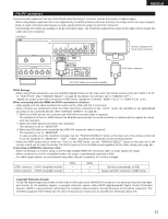
ENGLISH ENGLISH (2) Rear Panel @3 Audio output connectors (2ch AUDIO OUT) • Connect using the included audio cord. Multi-channel sound is down-mixed and output. @4 Component video output connectors (COMPONENT VIDEO OUT) • Connect using video cords (available in stores). @5 S-Video output connector (S-VIDEO OUT) • Connect using an S-Video connection cord (available in stores). @6 Video output connector (VIDEO OUT) • Connect using the included video cord. @7 HDMI output connector (HDMI) • Connect using HDMI (TYPE A) connection cord (available in stores). @8 DVI-D-Video output connector (DVI-D OUT) • Connect using 24P DVI-D connection cord (available in stores). @9 Audio output connectors (5.1ch AUDIO OUT) • Connect using an audio cord. Connect a commercially available pin-plug cord. #0 Digital connectors (IEEE1394) • This is for connection of a separately sold AV amplifier equipped with a IEEE 1394 connector. • Use it to achieve high quality digital sound with low data loss. #1 Control connector (RS-232C) • This is a terminal for future system expansion. #2 Control input connector (ROOM TO ROOM IN) • This is the input connector for wired remote control. Consult your DENON dealer if you wish to use this connector. #3 Control output connector (ROOM TO ROOM OUT) • This is the output connector for wired remote control. Consult your DENON dealer if you wish to use this connector. #4 Digital output connector (DENON LINK) • This is for connection of a separately sold AV amplifier equipped with a DENON LINK connector. • Use it to achieve high quality digital sound with low data loss. #5 Digital audio output connector (OPTICAL) • Connect using an optical fiber cable (available in stores). • Digital data is output from this connector. #6 Digital audio output connector (COAXIAL) • Connect using an digital audio cord. Connect a commercially available 75 Ω/ohms pin-plug cord. • Digital data is output from this connector. #7 Power input (AC IN) • Connect to AC power supply using the included power supply cord. (3) Display qw e r t y u i o !0 !1 !2 SUPER DVD GROUP TITLE TRACK CHAP ANGLE D.MIX PROG RAND TOTAL SING REM HDCD AUDIO VCD 1 A-B PROGRESSIVE F V DIGITAL L.PCMP.PCM L C R LFE MPEG JPEG SL S SR WMA MP3 HDMI IEEE1394 DVI !3 !4 !5 q Lights to indicate the currently playing disc. w Lights in the repeat play mode. e These light to indicate the names of sections of the disc being played. r Lights during playback of multiple angles disc. t Lights when the audio signals can be down-mixed. y Lights in the programmed play mode. u Lights in the random play mode. i There light to indicate the time display mode. o Lights when HDCD is playing. !0 Lights when SRS TruSurround is on. !1 Lights to indicate the currently playing audio format. !2 Lights to indicate the currently playing audio. L : Front left channel S : Mono surround channel C : Center channel SR : Surround right channel R : Front right channel LFE : Low frequency effect SL : Surround left channel !6 !7 !3 Lights to indicate the currently playing video type. F :Film source V :Video source !4 Lights when progressive video signals are being output. !5 Displays the title , track number and elapsed time during playback. !6 Lights when the audio signals is output from IEEE1394 terminals. !7 Lights when the video (or audio) signals is output via HDMI or DVI connectors. (Flashes while the connection to the HDMI/DVI-D connector is being checked.) 23
-
 1
1 -
2
-
3
-
4
-
5
-
6
-
7
-
8
-
9
-
10
-
11
-
12
-
13
-
14
-
15
-
16
-
17
-
 18
18 -
 19
19 -
 20
20 -
 21
21 -
 22
22 -
 23
23 -
 24
24 -
 25
25 -
 26
26 -
 27
27 -
 28
28 -
29
-
30
-
31
-
32
-
33
-
34
-
35
-
36
-
37
-
38
-
39
-
40
-
41
-
42
-
43
-
44
-
45
-
46
-
47
-
48
-
49
-
50
-
51
-
52
-
53
-
54
-
55
-
56
-
57
-
58
-
59
-
60
-
61
-
62
-
63
-
64
-
65
-
66
-
67
-
68
-
69
-
70
-
71
-
72
-
73
-
74
-
75
-
76
-
77
-
78
-
79
-
80
-
81
-
82
-
83
-
84
-
85
-
86
 |
 |
