Edimax IR-113E Manual - Page 9
DI/DO PIN ASSIGNMENT], Description - reset
 |
View all Edimax IR-113E manuals
Add to My Manuals
Save this manual to your list of manuals |
Page 9 highlights
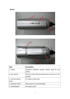
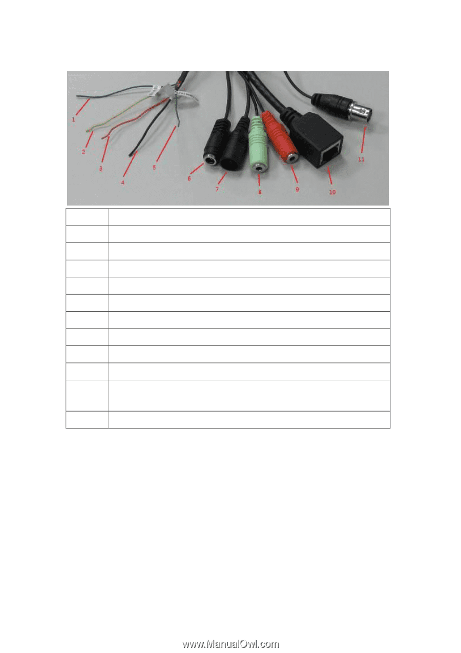
[DI/DO PIN ASSIGNMENT] Item Description 1 Blue, Sensor IN1, for alarm input, DV3.3Volt level allowed. 2 Yellow, RS485 D- 3 Orange, RS485 D+ 4 Black, GND 5 Green, Alarm out1, DV3.3Volt level allowed. 6 DC12Volt/2A input 7 Reset Button 8 Audio output 9 Audio input 10 Network, RJ45 connector, two LED index, orange color is power index, green is network index 11 TV output, BNC connector ※Please check the I/O cable attached index before insert or release any wire. 6
-
 1
1 -
2
-
3
-
 4
4 -
 5
5 -
 6
6 -
 7
7 -
 8
8 -
 9
9 -
 10
10 -
 11
11 -
 12
12 -
 13
13 -
 14
14 -
15
-
16
-
17
-
18
-
19
-
20
-
21
-
22
-
23
-
24
-
25
-
26
-
27
-
28
-
29
-
30
-
31
-
32
-
33
-
34
-
35
-
36
-
37
-
38
-
39
-
40
-
41
-
42
-
43
-
44
-
45
-
46
-
47
-
48
-
49
-
50
-
51
-
52
-
53
-
54
-
55
-
56
-
57
-
58
-
59
-
60
-
61
-
62
-
63
-
64
-
65
-
66
-
67
-
68
-
69
-
70
-
71
-
72
-
73
-
74
-
75
-
76
-
77
-
78
-
79
-
80
-
81
-
82
-
83
-
84
-
85
-
86
-
87
-
88
-
89
-
90
-
91
-
92
-
93
-
94
-
95
-
96
-
97
-
98
-
99
-
100
-
101
-
102
-
103
-
104
-
105
-
106
-
107
-
108
-
109
-
110
-
111
-
112
-
113
-
114
-
115
-
116
-
117
-
118
 |
 |
6
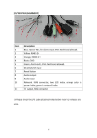
[DI/DO PIN ASSIGNMENT]
Item
Description
1
Blue, Sensor IN1, for alarm input, DV3.3Volt level allowed.
2
Yellow, RS485 D-
3
Orange, RS485 D+
4
Black, GND
5
Green, Alarm out1, DV3.3Volt level allowed.
6
DC12Volt/2A input
7
Reset Button
8
Audio output
9
Audio input
10
Network, RJ45 connector, two LED index, orange color is
power index, green is network index
11
TV output, BNC connector
※
Please check the I/O cable attached index before insert or release any
wire.