Fujitsu MHM2150AT Manual/User Guide
Fujitsu MHM2150AT - Mobile 15 GB Hard Drive Manual
 |
View all Fujitsu MHM2150AT manuals
Add to My Manuals
Save this manual to your list of manuals |
Fujitsu MHM2150AT manual content summary:
- Fujitsu MHM2150AT | Manual/User Guide - Page 1
C141-E104-03EN MHL2300AT, MHM2200AT, MHM2150AT, MHM2100AT DISK DRIVES PRODUCT MANUAL - Fujitsu MHM2150AT | Manual/User Guide - Page 2
TO USERS, BYSTANDERS OR PROPERTY. While FUJITSU has sought to ensure the accuracy of all information in this manual, FUJITSU assumes no liability to any party for or instructions contained herein; including any liability for incidental or consequential damages arising therefrom. FUJITSU DISCLAIMS - Fujitsu MHM2150AT | Manual/User Guide - Page 3
This page is intentionally left blank. - Fujitsu MHM2150AT | Manual/User Guide - Page 4
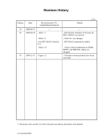
Revision History Edition Date Revised section (*1) (Added/Deleted/Altered) 01 2000-02-15 - 02 2000-09-20 - Table 1.1 - Table 1.2 - (16) SET MAX in Section 5.3.2 - Table 5.17 03 2000-12-13 - Figure 3.1 (1/1) Details - - Specification (Number of Sections for MHL2300AT) was altered. - Order No - Fujitsu MHM2150AT | Manual/User Guide - Page 5
This page is intentionally left blank. - Fujitsu MHM2150AT | Manual/User Guide - Page 6
describes the MHL Series and MHM Series, 2.5-inch hard disk drives. These drives have a built-in controller that is compatible with the ATA interface. This manual describes the specifications and functions of the drives and explains in detail how to incorporate the drives into user systems. This - Fujitsu MHM2150AT | Manual/User Guide - Page 7
environment of use, refer to the (Cnnn-Xnnn) and the (Cnnn-Xnnn). Attention Please forward any comments you may have regarding this manual. To make this manual easier for users to understand, opinions from readers are needed. Please write your opinions or requests on the Comment at the back of this - Fujitsu MHM2150AT | Manual/User Guide - Page 8
defects that involve adjustment, repair, or replacement. Fujitsu is not liable for any other disk drive defects, such as those caused by user misoperation or mishandling, inappropriate operating environments, defects in the power supply or cable, problems of the host system, or other causes outside - Fujitsu MHM2150AT | Manual/User Guide - Page 9
This page is intentionally left blank. - Fujitsu MHM2150AT | Manual/User Guide - Page 10
Important Alert Items Important Alert Messages The important alert messages in this manual are as follows: CAUTION A hazardous situation could result in minor or moderate personal injury if the user does not perform the procedure correctly. Also, damage - Fujitsu MHM2150AT | Manual/User Guide - Page 11
This page is intentionally left blank. - Fujitsu MHM2150AT | Manual/User Guide - Page 12
> • Device Overview • Device Configuration • Installation Conditions • Theory of Device Operation • Interface • Operations MHL2300AT, MHM2200AT, MHM2150AT, MHM2100AT DISK DRIVES MAINTENANCE MANUAL (C141-F043) • Maintenance and Diagnosis • Removal and Replacement Procedure C141-E104-03EN vii - Fujitsu MHM2150AT | Manual/User Guide - Page 13
This page is intentionally left blank. - Fujitsu MHM2150AT | Manual/User Guide - Page 14
Contents CHAPTER 1 Device Overview 1-1 1.1 Features 1-2 1.1.1 Functions and performance 1-2 1.1.2 Adaptability 1-2 1.1.3 Interface 1-3 1.2 Device Specifications 1-4 1.2.1 Specifications summary 1-4 1.2.2 Model and product number 1-5 1.3 Power Requirements 1-5 1.4 Environmental Specifications 1-7 - Fujitsu MHM2150AT | Manual/User Guide - Page 15
Contents CHAPTER 3 Installation Conditions 3-1 3.1 Dimensions 3-2 3.2 Mounting 3-4 3.3 Cable Connections 3-10 3.3.1 Device connector 3-10 3.3.2 Cable connector specifications 3-11 3.3.3 Device connection 3-11 3.3.4 Power supply connector (CN1) 3-12 3.4 Jumper Settings 3-12 3.4.1 Location of setting - Fujitsu MHM2150AT | Manual/User Guide - Page 16
4.6.2 4.6.3 4.6.4 Write circuit 4-11 Read circuit 4-13 Digital PLL circuit 4-14 4.7 Servo Control 4-15 4.7.1 Servo control circuit 4-15 4.7.2 Data-surface servo format 4-18 4.7.3 Servo frame format 4-20 4.7.4 Actuator motor control 4-21 4.7.5 Spindle motor control 4-22 Contents CHAPTER 5 - Fujitsu MHM2150AT | Manual/User Guide - Page 17
Contents 5.5.2.1 Ultra DMA burst initiation phase 5-93 5.5.2.2 Data transfer phase 5-94 5.5.2.3 Ultra DMA burst termination phase 5-94 5.5.3 Ultra DMA data in commands 5-95 5.5.3.1 Initiating an Ultra DMA data in burst 5-95 5.5.3.2 The data in transfer 5-96 5.5.3.3 Pausing an Ultra DMA data in - Fujitsu MHM2150AT | Manual/User Guide - Page 18
Glossary 6.1.1 Response to power-on 6-2 6.1.2 Response to hardware reset 6-4 6.1.3 Response to software reset 6-5 6.1.4 Response to diagnostic command 6-6 6.2 Address Translation 6-7 6.2.1 Default parameters 6-7 6.2.2 Logical address 6-8 6.3 Power Save 6-9 6.3.1 Power save mode 6-9 6.3.2 Power - Fujitsu MHM2150AT | Manual/User Guide - Page 19
3.3 Mounting frame structure 3-5 Figure 3.4 Location of breather 3-6 Figure 3.5 Surface temperature measurement points (Sample: MHL2300AT) 3-7 Figure 3.6 Service area (Sample: MHL2300AT) 3-8 Figure 3.7 Handling cautions 3-9 Figure 3.8 Connector locations (Sample: MHL2300AT) 3-10 Figure 3.9 Cable - Fujitsu MHM2150AT | Manual/User Guide - Page 20
Tables Contents Figure 5.3 Read Sector(s) command protocol 5-86 Figure 5.4 Protocol for command abort 5-87 Figure 5.5 WRITE SECTOR(S) command protocol 5-88 Figure 5.6 Protocol for the command execution without data transfer 5-90 Figure 5.7 Normal DMA data transfer 5-91 Figure 5.8 An example of - Fujitsu MHM2150AT | Manual/User Guide - Page 21
Contents Table 4.1 Self-calibration execution timechart 4-10 Table 4.2 Write precompensation algorithm 4-11 Table 5.1 Signal assignment on the interface connector 5-3 Table 5.2 I/O registers 5-7 Table 5.3 Command code and parameters 5-14 Table 5.4 Information to be read by IDENTIFY DEVICE command - Fujitsu MHM2150AT | Manual/User Guide - Page 22
CHAPTER 1 Device Overview 1.1 Features 1.2 Device Specifications 1.3 Power Requirements 1.4 Environmental Specifications 1.5 Acoustic Noise 1.6 Shock and Vibration 1.7 Reliability 1.8 Error Rate 1.9 Media Defects Overview and features are described in this chapter, and - Fujitsu MHM2150AT | Manual/User Guide - Page 23
GB (MHL2300AT), 20 GB (MHM2200AT), 15 GB (MHM2150AT) and 10 GB (MHM2100AT) respectively. (3) High-speed Transfer rate The disk drives (the MHL Series and MHM Series) have an internal data rate up to 28.7 MB/s. The disk drive supports - Fujitsu MHM2150AT | Manual/User Guide - Page 24
1.1 Features 1.1.3 Interface (1) Connection to interface With the built-in ATA interface controller, the disk drives (the MHL Series and MHM Series) can be connected to an ATA interface of a personal computer. (2) 2 MB data buffer The disk drives (the MHL Series and MHM Series) uses a 2 MB data - Fujitsu MHM2150AT | Manual/User Guide - Page 25
1.2.1 Specifications summary Table 1.1 shows the specifications of the disk drives (MHL Series and MHM Series). Table 1.1 Specifications (1/2) MHL2300AT MHM2200AT MHM2150AT MHM2100AT Format Capacity (*1) 30 GB 20 GB 15 GB 10 GB Number of Heads 6 4 3 2 Number of Cylinders (User) 19,904 - Fujitsu MHM2150AT | Manual/User Guide - Page 26
lists the model names and product numbers of the MHL Series and MHM Series. Table 1.2 Model names and product numbers Model Name MHL2300AT MHM2200AT MHM2150AT MHM2100AT Capacity (user area) 30 GB 20 GB 15 GB 10 GB Mounting screw M3, depth 3 M3, depth 3 M3, depth 3 M3, depth 3 Order No. CA05428 - Fujitsu MHM2150AT | Manual/User Guide - Page 27
2.45 W 2.3 W 0.25 W 0.25 W 0.1 W 0.1 W 0.032 W/GB 0.040 W/GB (rank E) (rank E / MHM2200AT) 0.040 W/GB (rank E / MHM2150AT) 0.080 W/GB (rank D / MHM2100AT) *1 Current at starting spindle motor. *2 At 30% disk accessing. *3 Power requirements reflect nominal values for +5V power. *4 Energy - Fujitsu MHM2150AT | Manual/User Guide - Page 28
1.4 Environmental Specifications Figure 1.1 Current fluctuation (Typ.) at +5V when power is turned on (5) Power on/off sequence The voltage detector circuits (the MHL Series and MHM Series) monitor +5 V. The circuits do not allow a write signal if either voltage is abnormal. These prevent data - Fujitsu MHM2150AT | Manual/User Guide - Page 29
Device Overview 1.5 Acoustic Noise Table 1.5 lists the acoustic noise specification. Table 1.5 Acoustic noise specification Item Sound Pressure • Idle mode (DRIVE READY) Specification 30 dBA typical at 1 m Note: Measure the noise from the cover top surface. 1.6 Shock and Vibration Table 1.6 - Fujitsu MHM2150AT | Manual/User Guide - Page 30
Mean time to repair (MTTR) The mean time to repair (MTTR) is 30 minutes or less, if repaired by a specialist maintenance staff member. (3) Service life In situations where management and handling are correct, the disk drive requires no overhaul for five years when the DE surface temperature is less - Fujitsu MHM2150AT | Manual/User Guide - Page 31
Device Overview 1.8 Error Rate Known defects, for which alternative blocks can be assigned, are not included in the error rate count below. It is assumed that the data blocks to be accessed are evenly distributed on the disk media. (1) Unrecoverable read error Read errors that cannot be recovered by - Fujitsu MHM2150AT | Manual/User Guide - Page 32
CHAPTER 2 Device Configuration 2.1 Device Configuration 2.2 System Configuration This chapter describes the internal configurations of the hard disk drives and the configuration of the systems in which they operate. C141-E104-03EN 2-1 - Fujitsu MHM2150AT | Manual/User Guide - Page 33
used varies with the model, as described below. The disks are rated at over 50,000 start/stop operations. MHL2300AT: 3 disks MHM2200AT: 2 disks MHM2150AT: 2 disks MHM2100AT: 1 disk The heads are of the contact start/stop (CSS) type. The head touches the disk surface while the disk is not rotating - Fujitsu MHM2150AT | Manual/User Guide - Page 34
2.1 Device Configuration Head 5 4 3 2 1 0 Head 3 2 1 0 Head 3 2 1 0 Head 1 0 MHL2300AT MHM2200AT MHM2150AT (Either of head 0 or MHM2100AT head 3 is mounted.) Figure 2.2 Configuration of disk media heads (3) Spindle motor The disks are rotated by a direct drive Hall-less DC motor. (4) - Fujitsu MHM2150AT | Manual/User Guide - Page 35
ATA interface system configuration. The drive has a 44pin PC AT interface connector and supports PIO mode 4 transfer at 16.6 MB/s, Multiword DMA mode 2 transfer at MB/s. 2.2.2 1 drive connection MHL2300AT MHMC22023020AATT MMHHMC22014500AATT MHM2100AT Figure 2.3 1 drive system configuration 2.2.3 2 - Fujitsu MHM2150AT | Manual/User Guide - Page 36
2.2 System Configuration IMPORTANT HA (host adaptor) consists of address decoder, driver, and receiver. ATA is an abbreviation of "AT attachment". The disk drive is conformed to the ATA-4 interface. At high speed data transfer (PIO mode 3, mode 4, or DMA mode 2 U-DMA mode 4), occurrence of ringing - Fujitsu MHM2150AT | Manual/User Guide - Page 37
This page is intentionally left blank. - Fujitsu MHM2150AT | Manual/User Guide - Page 38
CHAPTER 3 Installation Conditions 3.1 Dimensions 3.2 Mounting 3.3 Cable Connections 3.4 Jumper Settings This chapter gives the external dimensions, installation conditions, surface temperature conditions, cable connections, and switch settings of the hard disk drives. C141-E104-03EN 3-1 - Fujitsu MHM2150AT | Manual/User Guide - Page 39
Installation Conditions 3.1 Dimensions Figure 3.1 illustrates the dimensions of the disk drive and positions of the mounting screw holes. All dimensions are in mm. Figure 3.1 Dimensions (MHL series) (1/2) 3-2 C141-E104-03EN - Fujitsu MHM2150AT | Manual/User Guide - Page 40
3.1 Dimensions Figure 3.1 Dimensions (MHM series) (2/2) C141-E104-03EN 3-3 - Fujitsu MHM2150AT | Manual/User Guide - Page 41
Installation Conditions 3.2 Mounting (1) Orientation Figure 3.2 illustrates the allowable orientations for the disk drive. gravity (a) Horizontal -1 (b) Horizontal -1 gravity (c) Vertical -1 (d) Vertical -2 gravity (e) Vertical -3 (f) Vertical -4 Figure 3.2 Orientation (Sample: MHL2300AT) - Fujitsu MHM2150AT | Manual/User Guide - Page 42
3.2 Mounting (2) Frame The MR head bias of the HDD disk enclosure (DE) is zero. The mounting frame is connected to SG. IMPORTANT Use M3 screw for the mounting screw and the screw length should satisfy the specification in Figure 3.3. The tightening torque must be 0.49N·m(5kgf·cm). When attaching - Fujitsu MHM2150AT | Manual/User Guide - Page 43
Installation Conditions IMPORTANT Because of breather hole mounted to the HDD, do not allow this to close during mounting. Locating of breather hole is shown as Figure 3.4 in both MHL series and MHM series. For breather hole of Figure 3.4, at least, do not allow its around φ3 to block. Figure 3.4 - Fujitsu MHM2150AT | Manual/User Guide - Page 44
3.2 Mounting (4) Ambient temperature The temperature conditions for a disk drive mounted in a cabinet refer to the ambient temperature at a point 3 cm from the disk drive. The ambient temperature must satisfy the temperature conditions described in Section 1.4, and the airflow must be considered to - Fujitsu MHM2150AT | Manual/User Guide - Page 45
) during and after installation. Mounting screw hole Cable connection Mounting screw hole Figure 3.6 Service area (Sample: MHL2300AT) CAUTION Data corruption: Avoid mounting the disk drive near strong magnetic sources such as loud speakers. Ensure that the disk drive is - Fujitsu MHM2150AT | Manual/User Guide - Page 46
- General notes Wrist strap Use the Wrist strap. 3.2 Mounting ESD mat Shock absorbing mat Place the shock absorbing mat on the operation table, and place ESD mat on it. Do not hit HDD each other. Do not stack when carrying. Do not place HDD vertically to avoid falling down. Do not drop. Figure - Fujitsu MHM2150AT | Manual/User Guide - Page 47
Installation Conditions 3.3 Cable Connections 3.3.1 Device connector The disk drive has the connectors and terminals listed below for connecting external devices. Figure 3.8 shows the locations of these connectors and terminals. PCA Connector, setting pins Figure 3.8 Connector locations (Sample: - Fujitsu MHM2150AT | Manual/User Guide - Page 48
3.3 Cable Connections 3.3.2 Cable connector specifications Table 3.2 lists the recommended specifications for the cable connectors. Table 3.2 Cable connector specifications ATA interface and power supply cable (44-pin type) Name Cable socket (44-pin type) Model 89361-144 Manufacturer BERG - Fujitsu MHM2150AT | Manual/User Guide - Page 49
Installation Conditions 3.3.4 Power supply connector (CN1) Figure 3.10 shows the pin assignment of the power supply connector (CN1). Figure 3.10 Power supply connector pins (CN1) 3.4 Jumper Settings 3.4.1 Location of setting jumpers Figure 3.11 shows the location of the jumpers to select drive - Fujitsu MHM2150AT | Manual/User Guide - Page 50
3.4 Jumper Settings 3.4.2 Factory default setting Figure 3.12 shows the default setting position at the factory. Open Figure 3.12 Factory default setting 3.4.3 Master drive-slave drive setting Master drive (disk drive #0) or slave drive (disk drive #1) is selected. Open 1 CA 2 DB Open (a) - Fujitsu MHM2150AT | Manual/User Guide - Page 51
Installation Conditions 3.4.4 CSEL setting Figure 3.14 shows the cable select (CSEL) setting. Open 1 CA 2 DB Short Note: The CSEL setting is not depended on setting between pins Band D. Figure 3.14 CSEL setting Figure 3.15 and 3.16 show examples of cable selection using unique interface - Fujitsu MHM2150AT | Manual/User Guide - Page 52
3.4 Jumper Settings drive drive Figure 3.16 Example (2) of Cable Select C141-E104-03EN 3-15 - Fujitsu MHM2150AT | Manual/User Guide - Page 53
This page is intentionally left blank. - Fujitsu MHM2150AT | Manual/User Guide - Page 54
CHAPTER 4 Theory of Device Operation 4.1 Outline 4.2 Subassemblies 4.3 Circuit Configuration 4.4 Power-on Sequence 4.5 Self-calibration 4.6 Read/write Circuit 4.7 Servo Control This chapter explains basic design concepts of the disk drive. Also, this chapter explains subassemblies of - Fujitsu MHM2150AT | Manual/User Guide - Page 55
disks with an outer diameter of 65 mm and an inner diameter of 20 mm. The MHL2300AT have three disks and MHM2200AT and MHM2150AT have two disks and MHM2100AT have one disk. The head contacts the disk each time the disk rotation stops; the disk surface is durable at least 50,000 - Fujitsu MHM2150AT | Manual/User Guide - Page 56
4.2 Subassemblies Head 5 4 3 2 1 0 MHL2300AT Head 3 2 1 0 Head 3 2 1 0 MHM2200AT MHM2150AT (Either of head 0 or head 3 is mounted.) Figure 4.1 Head structure Head 1 0 MHK2100AT 4.2.3 Spindle The spindle consists of a disk stack assembly and spindle motor. The disk - Fujitsu MHM2150AT | Manual/User Guide - Page 57
Theory of Device Operation 4.3 Circuit Configuration Figure 4.2 shows the power supply configuration of the disk drive, and Figure 4.3 shows the disk drive circuit configuration. (1) Read/write circuit The read/write circuit consists of two LSIs; read/write preamplifier (PreAMP) and read channel ( - Fujitsu MHM2150AT | Manual/User Guide - Page 58
4.3 Circuit Configuration 5V HDC SVC 3.3V HDIC - 3V MCU FROM SDRAM RDC Figure 4.2 Power Supply Configuration C141-E104-03EN 4-5 - Fujitsu MHM2150AT | Manual/User Guide - Page 59
Theory of Device Operation Printed Circuit Board FROM Program Memory 16 bit Local Bus Host ATA Interface HDC (Hard Disk Controller) 16 bit Data Buffer Bus Read and Write Data RDC Control Signal MPU (Micro Processor Unit) HDIC Control Signal SVC Control Signal SDRAM Data Buffer RAM RDC - Fujitsu MHM2150AT | Manual/User Guide - Page 60
4.3 Circuit Configuration 4.4 Power-on Sequence Figure 4.4 describes the operation sequence of the disk drive at power-on. The outline is described below. a) After the power is turned on, the disk drive executes the MPU bus test, internal register read/write test, and work RAM read/write test. When - Fujitsu MHM2150AT | Manual/User Guide - Page 61
Theory of Device Operation Power-on Start a) Self-diagnosis 1 - MPU bus test - Internal register write/read test - Work RAM write/read test The spindle motor starts. b) Self-diagnosis 2 - Data buffer write/read test c) Confirming spindle motor speed Releasing heads from Actuator - Fujitsu MHM2150AT | Manual/User Guide - Page 62
4.5 Self-calibration The forces are compensated by adding the measured value to the specified current value to the power amplifier. This makes the stable servo control. To compensate torque varying by the cylinder, the disk is divided into 23 areas from the innermost to the outermost circumference - Fujitsu MHM2150AT | Manual/User Guide - Page 63
to the timechart, the disk drive terminates self-calibration and starts executing the command precedingly. In other words, if a disk read or write service is necessary, the disk drive positions the head to the track requested by the host, reads or writes data, and restarts calibration. This enables - Fujitsu MHM2150AT | Manual/User Guide - Page 64
4.6 Read/write Circuit 4.6.2 Write circuit The write data is output from the hard disk controller (HDC) with the NRZ data format, and sent to the encoder circuit in the RDC. The NRZ write data is converted from 16-bit data to 17-bit data by the encoder circuit then sent to the HDIC, and the data is - Fujitsu MHM2150AT | Manual/User Guide - Page 65
Theory of Device Operation HDIC WDX/WDY RDC Write PreCompensation SD SC SE Serial I/O Registers Digital PLL Flash Digitizer RDX/RDY AGC Amplifier Programmable Filter MEEPR Viterbi Detect ServoPulse Detector 16/17 ENDEC Position A/B/C/D (to reg) WTGATE REFCLK RDGATE DATA RWCLK SRV_CLK - Fujitsu MHM2150AT | Manual/User Guide - Page 66
the read signal. Cut-off frequency of the low-pass filter and boost-up gain are controlled from the register in read channel by an instruction of the serial data signal from MPU (M5). The MPU optimizes the cut-off frequency and boost-up gain according to the transfer frequency of - Fujitsu MHM2150AT | Manual/User Guide - Page 67
Theory of Device Operation (3) Flash digitizer circuit This circuit is 10-tap sampled analog transversal filter circuit that cosine-equalizes the head read signal to the Modified Extended Partial Response (MEEPR) waveform. (4) Viterbi detection circuit The sample hold waveform output from the flash - Fujitsu MHM2150AT | Manual/User Guide - Page 68
4.6 Read/write Circuit 4.7 Servo Control The actuator motor and the spindle motor are submitted to servo control. The actuator motor is controlled for moving and positioning the head to the track containing the desired data. To turn the disk at a constant velocity, the actuator motor is controlled - Fujitsu MHM2150AT | Manual/User Guide - Page 69
Theory of Device Operation The major internal operations are listed below. a. Spindle motor start Starts the spindle motor and accelerates it to normal speed when power is applied. b. Move head to reference cylinder Drives the VCM to position the head at the any cylinder in the data area. The - Fujitsu MHM2150AT | Manual/User Guide - Page 70
4.7 Servo Control (2) Servo burst capture circuit The servo burst capture circuit reproduces signals (position signals) that indicate the head position from the servo data on the data surface. SERVO A, SERVO B, SERVO C and SERVO D burst signals shown in Figure 4.9 followed the servo mark, cylinder - Fujitsu MHM2150AT | Manual/User Guide - Page 71
Theory of Device Operation 4.7.2 Data-surface servo format Figure 4.8 describes the physical layout of the servo frame. The three areas indicated by (1) to (3) in Figure 4.8 are described below. (1) Inner guard band The head is in contact with the disk in this space when the spindle starts turning - Fujitsu MHM2150AT | Manual/User Guide - Page 72
4.7 Servo Control Servo frame (66 servo frames per revolution) IGB Data area expand OGB CYLn + 1 CYLn CYLn - 1 (n: even number) W/R Recovery Servo Mark Gray Code W/R Recovery Servo Mark Gray Code W/R Recovery Servo Mark Gray Code Erase Servo A Erase Servo A Servo B Erase Servo B - Fujitsu MHM2150AT | Manual/User Guide - Page 73
Theory of Device Operation 4.7.3 Servo frame format As the servo information, the IDD uses the two-phase servo generated from the gray code and servo A to D. This servo information is used for positioning operation of radius direction and position detection of circumstance direction. The servo frame - Fujitsu MHM2150AT | Manual/User Guide - Page 74
4.7 Servo Control (1) Write/read recovery This area is used to absorb the write/read transient and to stabilize the AGC. (2) Servo mark This area generates a timing for demodulating the gray code and positiondemodulating the servo A to D by detecting the servo mark. (3) Gray code (including index - Fujitsu MHM2150AT | Manual/User Guide - Page 75
the MPU confirms the necessity of access to the disk. If a read/write instruction is issued, the MPU seeks the desired track. The MPU feeds the VCM (called SVC hereafter). The firmware operates on the MPU manufactured by Fujitsu. The spindle motor is controlled by sending several signals from the - Fujitsu MHM2150AT | Manual/User Guide - Page 76
4.7 Servo Control d) During phase switching, the spindle motor starts rotating in low speed, and generates a counter electromotive force. The SVC detects this counter electromotive force and reports to the MPU using a PHASE signal for speed detection. e) The MPU is waiting for a PHASE signal. When - Fujitsu MHM2150AT | Manual/User Guide - Page 77
This page is intentionally left blank. - Fujitsu MHM2150AT | Manual/User Guide - Page 78
CHAPTER 5 Interface 5.1 Physical Interface 5.2 Logical Interface 5.3 Host Commands 5.4 Command Protocol 5.5 Ultra DMA Feature Set 5.6 Timing This chapter gives details about the interface, and the interface commands and timings. C141-E104-03EN 5-1 - Fujitsu MHM2150AT | Manual/User Guide - Page 79
Interface 5.1 Physical Interface 5.1.1 Interface signals Figure 5.1 shows the interface signals. Host DATA 0-15: DATA BUS IDD DMACK-: DMA ACKNOWLEDGE DMARQ: DMA REQUEST INTRO: INTERRUPT REQUEST DIOW-: I/O WRITE STOP: STOP DURING ULTRA DMA DATA BURSTS DIOR-:I/O READ HDMARDY:DMA READY DURING - Fujitsu MHM2150AT | Manual/User Guide - Page 80
5.1 Physical Interface 5.1.2 Signal assignment on the connector Table 5.1 shows the signal assignment on the interface connector. Table 5.1 Signal assignment on the interface connector Pin No. A C E 1 3 5 7 9 11 13 15 17 19 21 23 25 27 29 31 33 35 37 39 41 43 Signal MSTR unused (KEY) RESET- - Fujitsu MHM2150AT | Manual/User Guide - Page 81
Interface [signal] ENCSEL MSTRRESETDATA 0-15 DIOWSTOP DIORHDMARDY- HSTROBE INTRQ [I/O] I I I I/O I I I I I O [Description] This signal is used to set master/slave using the CSEL signal (pin 28). Pins B and D Open: Sets master/slave using the CSEL signal is disabled. Short: Sets master/slave using - Fujitsu MHM2150AT | Manual/User Guide - Page 82
5.1 Physical Interface [signal] CS0CS1DA 0-2 KEY PDIAG- CBLIDDASPIORDY DDMARDY - DSTROBE CSEL DMACK- [I/O] I I I I/O I/O I/O O O O I I [Description] Chip select signal decoded from the host address bus. This signal is used by the host to select the command block registers. Chip select signal - Fujitsu MHM2150AT | Manual/User Guide - Page 83
in either address-specified mode; cylinder-head-sector (CHS) or Logical block address (LBA) mode. The IDENTIFY DEVICE information indicates whether the device supports the LBA mode. When the host system specifies the LBA mode by setting bit 6 in the Device/Head register to 1, HS3 to HS0 bits - Fujitsu MHM2150AT | Manual/User Guide - Page 84
5.2 Logical Interface 5.2.1 I/O registers Communication between the host system and the device is done through inputoutput (I/O) registers of the device. These I/O registers can be selected by the coded signals, CS0-, CS1-, and DA0 to DA2 from the host system. Table 5.2. shows the coding address - Fujitsu MHM2150AT | Manual/User Guide - Page 85
Interface 5.2.2 Command block registers (1) Data register (X'1F0') The Data register is a 16-bit register for data block transfer between the device and the host system. Data transfer mode is PIO or DMA mode. (2) Error register (X'1F1') The Error register indicates the status of the command - Fujitsu MHM2150AT | Manual/User Guide - Page 86
5.2 Logical Interface [Diagnostic code] X'01': X'02': X'03': X'05': X'80': No Error Detected. HDC Register Compare Error Data Buffer Compare Error. ROM Sum Check Error. Device 1 (slave device) Failed. Error register of the master device is valid under two devices (master and slave) configuration. - Fujitsu MHM2150AT | Manual/User Guide - Page 87
Interface (6) Cylinder Low register (X'1F4') The contents of this register indicates low-order 8 bits of the starting cylinder address for any disk-access. At the end of a command, the contents of this register are updated to the current cylinder number. Under the LBA mode, this register indicates - Fujitsu MHM2150AT | Manual/User Guide - Page 88
5.2 Logical Interface (9) Status register (X'1F7') The contents of this register indicate the status of the device. The contents of this register are updated at the completion of each command. When the BSY bit is cleared, other bits in this register should be validated within 400 ns. When the BSY - Fujitsu MHM2150AT | Manual/User Guide - Page 89
Interface - Bit 5: - Bit 4: The Device Write Fault (DF) bit. This bit indicates that a device fault (write fault) condition has been detected. If a write fault is detected during command execution, this bit is latched and retained until the device accepts the next command or reset. Device Seek - Fujitsu MHM2150AT | Manual/User Guide - Page 90
5.3 Host Commands 5.2.3 Control block registers (1) Alternate Status register (X'3F6') The Alternate Status register contains the same information as the Status register of the command block register. The only difference from the Status register is that a read of this register does not imply - Fujitsu MHM2150AT | Manual/User Guide - Page 91
system writes to the command register, the correct device operation is not guaranteed. 5.3.1 Command code and parameters Table 5.3 lists the supported commands, command code and the registers that needed parameters are written. Table 5.3 Command code and parameters (1 of 2) Command name 7 READ - Fujitsu MHM2150AT | Manual/User Guide - Page 92
5.3 Host Commands Table 5.3 Command code and parameters (2 of 2) Command name Command code (Bit) Parameters used 7 6 5 4 3 2 1 0 FR SC SN CY DH IDLE IMMEDIATE 1 0 0 1 0 1 0 1 NNNND 11100001 STANDBY 1 0 0 1 0 1 1 0 NYNND 11100010 STANDBY IMMEDIATE 1 0 0 1 0 1 0 0 NNNND 11100000 SLEEP 1 0 - Fujitsu MHM2150AT | Manual/User Guide - Page 93
Interface Y*: Necessary to set parameters under the LBA mode. N: Not necessary to set parameters (The parameter is ignored if it is set.) N*: May set parameters D: The device parameter is valid, and the head parameter is ignored. D*: The command is addressed to the master device, but both the master - Fujitsu MHM2150AT | Manual/User Guide - Page 94
5.3 Host Commands CM: Command register FR: Features register DH: Device/Head register ST: Status register CH: Cylinder High register ER: Error register CL: Cylinder Low register L: LBA (logical block address) setting bit SN: Sector Number register DV: Device address. bit SC: Sector Count - Fujitsu MHM2150AT | Manual/User Guide - Page 95
Interface Command block registers contain the cylinder, the head, and the sector addresses of the sector (in the CHS mode) or the logical block address (in the LBA mode) where the error occurred, and remaining number of sectors of which data was not transferred. At command issuance (I/O registers - Fujitsu MHM2150AT | Manual/User Guide - Page 96
5.3 Host Commands The implementation of the READ MULTIPLE command is identical to that of the READ SECTOR(S) command except that the number of sectors is specified by the SET MULTIPLE MODE command are transferred without intervening interrupts. In the READ MULTIPLE command operation, the DRQ bit of - Fujitsu MHM2150AT | Manual/User Guide - Page 97
Interface Figure 5.2 Execution example of READ MULTIPLE command At command issuance (I/O registers setting contents) 1F7H(CM) 1F6H(DH) 1F5H(CH) 1F4H(CL) 1F3H(SN) 1F2H(SC) 1F1H(FR) 11000100 x L x DV Start head No. /LBA [MSB] Start cylinder No. [MSB] / LBA Start cylinder No. [LSB] / LBA Start - Fujitsu MHM2150AT | Manual/User Guide - Page 98
5.3 Host Commands (3) READ DMA (X'C8' or X'C9') This command operates similarly to the READ SECTOR(S) command except for following events. • The data transfer starts at the timing of DMARQ signal assertion. • The device controls the assertion or negation timing of the DMARQ signal. • The device - Fujitsu MHM2150AT | Manual/User Guide - Page 99
Interface At command completion (I/O registers contents to be read) 1F7H(ST) 1F6H(DH) 1F5H(CH) 1F4H(CL) 1F3H(SN) 1F2H(SC) 1F1H(ER) Status information x L x DV End head No. /LBA [MSB] End cylinder No. [MSB] / LBA End cylinder No. [LSB] / LBA End sector No. / LBA [LSB] 00 (*1) Error information *1 - Fujitsu MHM2150AT | Manual/User Guide - Page 100
5.3 Host Commands At command issuance (I/O registers setting contents) 1F7H(CM) 1F6H(DH) 1F5H(CH) 1F4H(CL) 1F3H(SN) 1F2H(SC) 1F1H(FR) 0 1 0 0 0 0 0R x L x DV Start head No. /LBA [MSB] Start cylinder No. [MSB] / LBA Start cylinder No. [LSB] / LBA Start sector No. / LBA [LSB] Transfer sector count - Fujitsu MHM2150AT | Manual/User Guide - Page 101
Interface If an error occurs during multiple sector write operation, the write operation is terminated at the sector where the error occurred. Command block registers contain the cylinder, the head, the sector addresses (in the CHS mode) or the logical block address (in the LBA mode) of the sector - Fujitsu MHM2150AT | Manual/User Guide - Page 102
5.3 Host Commands (6) WRITE MULTIPLE (X'C5') This command is similar to the WRITE SECTOR(S) command. The device does not generate interrupts (assertion of the INTRQ) signal) on each sector but on the transfer of a block which contains the number of sectors for which the number is defined by the SET - Fujitsu MHM2150AT | Manual/User Guide - Page 103
Interface At command issuance (I/O registers setting contents) 1F7H(CM) 1F6H(DH) 1F5H(CH) 1F4H(CL) 1F3H(SN) 1F2H(SC) 1F1H(FR) 11000101 x L x DV Start head No. /LBA [MSB] Start cylinder No. [MSB] / LBA Start cylinder No. [LSB] / LBA Start sector No. / LBA [LSB] Transfer sector count xx At command - Fujitsu MHM2150AT | Manual/User Guide - Page 104
5.3 Host Commands A host system can select the following transfer mode using the SET FEATURES command. • Multiword DMA transfer mode 0 to 2 • Ultra DMA transfer mode 0 to 4 At command issuance (I/O registers setting contents) 1F7H(CM) 1F6H(DH) 1F5H(CH) 1F4H(CL) 1F3H(SN) 1F2H(SC) 1F1H(FR) 1 1 0 0 - Fujitsu MHM2150AT | Manual/User Guide - Page 105
Interface At command issuance (I/O registers setting contents) 1F7H(CM) 1F6H(DH) 1F5H(CH) 1F4H(CL) 1F3H(SN) 1F2H(SC) 1F1H(FR) 00111100 x L x DV Start head No. /LBA [MSB] Start cylinder No. [MSB] / LBA Start cylinder No. [LSB] / LBA Start sector No. / LBA [LSB] Transfer sector count xx At command - Fujitsu MHM2150AT | Manual/User Guide - Page 106
5.3 Host Commands At command issuance (I/O registers setting contents) 1F7H(CM) 0 0 0 1 x x x x 1F6H(DH) x x x DV xx 1F5H(CH) xx 1F4H(CL) xx 1F3H(SN) xx 1F2H(SC) xx 1F1H(FR) xx At command completion (I/O registers contents to be read) 1F7H(ST) 1F6H(DH) 1F5H(CH) 1F4H(CL) 1F3H(SN) 1F2H(SC) 1F1H(ER) - Fujitsu MHM2150AT | Manual/User Guide - Page 107
Interface At command issuance (I/O registers setting contents) 1F7H(CM) 1F6H(DH) 1F5H(CH) 1F4H(CL) 1F3H(SN) 1F2H(SC) 1F1H(FR) 0111xxxx x L x DV Head No. /LBA [MSB] Cylinder No. [MSB] / LBA Cylinder No. [LSB] / LBA Sector No. / LBA [LSB] xx xx At command completion (I/O registers contents to be - Fujitsu MHM2150AT | Manual/User Guide - Page 108
5.3 Host Commands At command issuance (I/O registers setting contents) 1F7H(CM) 1 0 0 1 0 0 0 1 1F6H(DH) x x x DV Max. head No. 1F5H(CH) xx 1F4H(CL) xx 1F3H(SN) xx 1F2H(SC) Number of sectors/track 1F1H(FR) xx At command completion (I/O registers contents to be read) 1F7H(ST) 1F6H(DH) 1F5H(CH) - Fujitsu MHM2150AT | Manual/User Guide - Page 109
Interface At command issuance (I/O registers setting contents) 1F7H(CM) 1 1 1 0 1 1 0 0 1F6H(DH) x x x DV xx 1F5H(CH) xx 1F4H(CL) xx 1F3H(SN) xx 1F2H(SC) xx 1F1H(FR) xx At command completion (I/O registers contents to be read) 1F7H(ST) 1F6H(DH) 1F5H(CH) 1F4H(CL) 1F3H(SN) 1F2H(SC) 1F1H(ER) Status - Fujitsu MHM2150AT | Manual/User Guide - Page 110
MULTIPLE command *6 Total number of user addressable sectors (LBA mode only) *2 Reserved Multiword DMA transfer mode *7 Advance PIO transfer mode support status *8 Minimum multiword DMA transfer cycle time per word : 120 [ns] Manufacturer's recommended DMA transfer cycle time : 120 [ns] Minimum - Fujitsu MHM2150AT | Manual/User Guide - Page 111
*2 Word 1, 3, 6, 60-61 Word 01 Word 03 Word 06 Word 60-61 MHL2300AT X'3FFF' X'10' X'3F' X'37E3E40' *3 Word 49: Capabilities MHM2200AT X'3FFF' X'10' X'3F' X'2542980' MHM2150AT X'3FFF' X'10' X'3F' X'1C21B00' Bit 15-14: Reserved MHM2100AT X'3FFF' X'10' X'3F' X'12BB230' 5-34 C141-E104-03EN - Fujitsu MHM2150AT | Manual/User Guide - Page 112
to be read by IDENTIFY DEVICE command (4 of 8) Bit 13: Standby timer value. Factory default is 0. Bit 12: Reserved Bit 11: IORDY support 1=Supported Bit 10: IORDY inhibition 0=Disable inhibition Bit 9-0: Undefined Bit 9, 8: Always 1 *4 Word 51: PIO data transfer mode Bit 15-8: PIO data - Fujitsu MHM2150AT | Manual/User Guide - Page 113
WRITE BUFFER command. Bit 11: Undefined Bit 10: '1' = Supports the Host Protected Area feature set. Bit 9: '1' = Supports the DEVICE RESET command. Bit 8: '1' = Supports the SERVICE interrupt. Bit 7: '1' = Supports the release interrupt. Bit 6: '1' = Supports the read cache function. Bit - Fujitsu MHM2150AT | Manual/User Guide - Page 114
Supports the Power-Up In Standby set. Bit 4: '1' = Supports the Removable Media Status Notification feature set. Bit 3: '1' = Supports the Advanced Power Management feature set. Bit 2: '1' = Supports RESET command. Bit 8: '1' = Enables the SERVICE interrupt. Bit 7: '1' = Enables the release - Fujitsu MHM2150AT | Manual/User Guide - Page 115
command (7 of 8) Bits 2-0: Same definition as WORD 83. *14 WORD 88 Bit 15-8: Currently used Ultra DMA transfer mode Bit 7-0: Supportable Ultra DMA transfer mode Bit 4 = '1': Mode 4 Bit 3 = '1': Mode 3 Bit 2 = '1': Mode 2 Bit 1 = '1': Mode 1 Bit 0 = '1': Mode 0 *15 WORD 93 Bits 15-14 - Fujitsu MHM2150AT | Manual/User Guide - Page 116
0: Reserved *16 WORD 128 Bit 15-9: Reserved Bit 8: Security level. 0: High, 1: Maximum Bit 7-6: Reserved Bit 5: 1: Enhanced security erase supported Bit 4: 1: Security counter expired Bit 3: 1: Security frozen Bit 2: 1: Security locked Bit 1: 1: Security enabled Bit 0: 1: Security - Fujitsu MHM2150AT | Manual/User Guide - Page 117
parameters in the Features register. Then, the device clears the BSY bit, and generates an interrupt. If the value in the Features register is not supported or it is invalid, the device posts an ABORTED COMMAND error. Table 5.5 lists the available values and operational modes that may be set in the - Fujitsu MHM2150AT | Manual/User Guide - Page 118
5.3 Host Commands Table 5.5 Features register values and settable modes Features Register X'02' X'03' X'05' X'55' X'66' X'82' X'85' X'AA' X'BB' X'CC' Drive operation mode Enables the write cache function. Transfer mode depends on the contents of the Sector Count register. (Details are given later - Fujitsu MHM2150AT | Manual/User Guide - Page 119
be selected. Upper 5 bits of the Sector Count register defines the transfer type and lower 3 bits specifies the binary mode value. The IDD supports following values in the Sector Count register value. If other value than below is specified, an ABORTED COMMAND error is posted. PIO default transfer - Fujitsu MHM2150AT | Manual/User Guide - Page 120
commands are also specified by the SET MULTIPLE MODE command. The number of sectors per block is written into the Sector Count register. The IDD supports 2, 4, 8, 16 and 32 (sectors) as the block counts. Upon receipt of this command, the device sets the BSY bit of the Status register and checks - Fujitsu MHM2150AT | Manual/User Guide - Page 121
Interface At command issuance (I/O registers setting contents) 1F7H(CM) 1 1 0 0 0 1 1 0 1F6H(DH) x x x DV xx 1F5H(CH) xx 1F4H(CL) xx 1F3H(SN) xx 1F2H(SC) Sector count/block 1F1H(FR) xx At command completion (I/O registers contents to be read) 1F7H(ST) 1F6H(DH) 1F5H(CH) 1F4H(CL) 1F3H(SN) 1F2H(SC) - Fujitsu MHM2150AT | Manual/User Guide - Page 122
5.3 Host Commands Word 47 Bit 7-0 = 10: Word 59 = 0000: = 01xx: Maximum number of sectors that can be transferred per interrupt by the READ MULTIPLE and WRITE MULTIPLE commands. The READ MULTIPLE and WRITE MULTIPLE commands are disabled. The READ MULTIPLE and WRITE MULTIPLE commands are enabled. " - Fujitsu MHM2150AT | Manual/User Guide - Page 123
Interface After power on and the occurrence of a hard reset, the host can issue this command only once when VV bit = 1. If this command with VV bit = 1 is issued twice or more, any command following the first time will result in an Aborted Command error. At command issuance (I/O registers setting - Fujitsu MHM2150AT | Manual/User Guide - Page 124
5.3 Host Commands At command issuance (I/O registers setting contents) 1F7H(CM) 1 1 1 1 1 0 0 1 1F6H(DH) x L x DV xx 1F5H(CH) xx 1F4H(CL) xx 1F3H(SN) xx 1F2H(SC) xx 1F1H(FR) 01 At command completion (I/O registers contents to be read) 1F7H(ST) 1F6H(DH) 1F5H(CH) 1F4H(CL) 1F3H(SN) 1F2H(SC) 1F1H(ER) - Fujitsu MHM2150AT | Manual/User Guide - Page 125
Interface If the device is in the Set Max Locked or Set Max Freeze Locked state: 51h, 04h: ABORTED command At command issuance (I/O registers setting contents) 1F7H(CM) 1 1 1 1 1 0 0 1 1F6H(DH) x L x DV xx 1F5H(CH) xx 1F4H(CL) xx 1F3H(SN) xx 1F2H(SC) xx 1F1H(FR) 02 At command completion (I/O - Fujitsu MHM2150AT | Manual/User Guide - Page 126
5.3 Host Commands If this command is accepted in the Set Max Unlocked state, the device terminates normally. The READ NATIVE MAX ADDRESS command is not executed just before this command. The command is the SET MAX ADDRESS command if it is the command just after the READ NATIVE MAX ADDRESS command is - Fujitsu MHM2150AT | Manual/User Guide - Page 127
Interface The READ NATIVE MAX ADDRESS command is not executed just before this command. The command is the SET MAX ADDRESS command if it is the command just after the READ NATIVE MAX ADDRESS command is executed. At command issuance (I/O registers setting contents) 1F7H(CM) 1 1 1 1 1 0 0 1 1F6H(DH) - Fujitsu MHM2150AT | Manual/User Guide - Page 128
5.3 Host Commands At command issuance (I/O registers setting contents) 1F7H(CM) 1 1 1 1 1 0 0 0 1F6H(DH) x L x DV xx 1F5H(CH) xx 1F4H(CL) xx 1F3H(SN) xx 1F2H(SC) xx 1F1H(FR) xx At command completion (I/O registers contents to be read) 1F7H(ST) 1F6H(DH) 1F5H(CH) 1F4H(CL) 1F3H(SN) 1F2H(SC) 1F1H(ER) - Fujitsu MHM2150AT | Manual/User Guide - Page 129
Interface When device 1 is not present: • The device 0 posts only the results of its own self-diagnosis. • The device 0 clears the BSY bit of the Status register, and generates an interrupt. Table 5.6 lists the diagnostic code written in the Error register which is 8-bit code. If the device 1 fails - Fujitsu MHM2150AT | Manual/User Guide - Page 130
command. Number of ECC bytes to be transferred is fixed to 4 bytes and cannot be changed by the SET FEATURES command. The READ LONG command supports only single sector operation. At command issuance (I/O registers setting contents) 1F7H(CM) 1F6H(DH) 1F5H(CH) 1F4H(CL) 1F3H(SN) 1F2H(SC) 1F1H(FR - Fujitsu MHM2150AT | Manual/User Guide - Page 131
the ECC bytes transferred from the host system to the disk medium. The device does not generate ECC bytes by itself. The WRITE LONG command supports only single sector operation. The number of ECC bytes to be transferred is fixed to 4 bytes and can not be changed by the SET FEATURES - Fujitsu MHM2150AT | Manual/User Guide - Page 132
5.3 Host Commands At command completion (I/O registers contents to be read) 1F7H(ST) 1F6H(DH) 1F5H(CH) 1F4H(CL) 1F3H(SN) 1F2H(SC) 1F1H(ER) Status information x L x DV Head No. /LBA [MSB] Cylinder No. [MSB] / LBA Cylinder No. [LSB] / LBA Sector No. / LBA [LSB] 00 (*1) Error information *1 If the - Fujitsu MHM2150AT | Manual/User Guide - Page 133
Interface At command completion (I/O registers contents to be read) 1F7H(ST) 1F6H(DH) 1F5H(CH) 1F4H(CL) 1F3H(SN) 1F2H(SC) 1F1H(ER) Status information x x x DV xx xx xx xx xx Error information (22) WRITE BUFFER (X'E8') The host system can overwrite the contents of the sector buffer of the device - Fujitsu MHM2150AT | Manual/User Guide - Page 134
5.3 Host Commands At command completion (I/O registers contents to be read) 1F7H(ST) 1F6H(DH) 1F5H(CH) 1F4H(CL) 1F3H(SN) 1F2H(SC) 1F1H(ER) Status information x x x DV xx xx xx xx xx Error information (23) IDLE (X'97' or X'E3') Upon receipt of this command, the device sets the BSY bit of the - Fujitsu MHM2150AT | Manual/User Guide - Page 135
bit of the Status register, and enters the idle mode. Then, the device clears the BSY bit, and generates an interrupt. This command does not support the automatic power-down function. At command issuance (I/O registers setting contents) 1F7H(CM) 1F6H(DH) 1F5H(CH) 1F4H(CL) 1F3H(SN) 1F2H(SC) 1F1H(FR - Fujitsu MHM2150AT | Manual/User Guide - Page 136
5.3 Host Commands At command completion (I/O registers contents to be read) 1F7H(ST) 1F6H(DH) 1F5H(CH) 1F4H(CL) 1F3H(SN) 1F2H(SC) 1F1H(ER) Status information x x x DV xx xx xx xx xx Error information (25) STANDBY (X'96' or X'E2') Upon receipt of this command, the device sets the BSY bit of the - Fujitsu MHM2150AT | Manual/User Guide - Page 137
bit of the Status register and enters the standby mode. The device then clears the BSY bit and generates an interrupt. This command does not support the automatic power-down sequence. At command issuance (I/O registers setting contents) 1F7H(CM) 1F6H(DH) 1F5H(CH) 1F4H(CL) 1F3H(SN) 1F2H(SC) 1F1H(FR - Fujitsu MHM2150AT | Manual/User Guide - Page 138
5.3 Host Commands (27) SLEEP (X'99' or X'E6') This command is the only way to make the device enter the sleep mode. Upon receipt of this command, the device sets the BSY bit of the Status register and enters the sleep mode. The device then clears the BSY bit and generates an interrupt. The device - Fujitsu MHM2150AT | Manual/User Guide - Page 139
Interface (28) CHECK POWER MODE (X'98' or X'E5') The host checks the power mode of the device with this command. The host system can confirm the power save mode of the device by analyzing the contents of the Sector Count and Sector registers. The device sets the BSY bit and sets the following - Fujitsu MHM2150AT | Manual/User Guide - Page 140
) This command performs operations for device failure predictions according to a subcommand specified in the FR register. If the value specified in the FR register is supported, the Aborted Command error is posted. It is necessary for the host to set the keys (CL = 4Fh and CH = C2h) in the CL and - Fujitsu MHM2150AT | Manual/User Guide - Page 141
Interface Table 5.7 Features Register values (subcommands) and functions (1 of 3) Features Resister X'D0' X'D1' X'D2' X'D3' X'D4' Function SMART Read Attribute Values: A device that received this subcommand asserts the BSY bit and saves all the updated attribute values. The device then clears the - Fujitsu MHM2150AT | Manual/User Guide - Page 142
5.3 Host Commands Table 5.7 Features Register values (subcommands) and functions (2 of 3) Features Resister X'D5' Function SMART Read Log Sector: A device which receives this sub-command asserts the BSY bit, then reads the log sector specified in the SN register. Next, it clears the BSY bit and - Fujitsu MHM2150AT | Manual/User Guide - Page 143
Interface Table 5.7 Features Register values (subcommands) and functions (3 of 3) Features Resister X'DA' X'DB' Function SMART Return Status: When the device receives this subcommand, it asserts the BSY bit and saves the current device attribute values. Then the device compares the device - Fujitsu MHM2150AT | Manual/User Guide - Page 144
5.3 Host Commands At command completion (I-O registers setting contents) 1F7H(ST) 1F6H(DH) 1F5H(CH) 1F4H(CL) 1F3H(SN) 1F2H(SC) 1F1H(ER) Status information x x x DV xx Key-failure prediction status (C2h-2Ch) Key-failure prediction status (4Fh-F4h) xx xx Error information The attribute value - Fujitsu MHM2150AT | Manual/User Guide - Page 145
collection status Self test execution status Off-line data collection execution time [sec.] Reserved Off-line data collection capability Trouble prediction capability flag Error logging capability Vendor unique Simple self test execution time [min.] Comprehensive self test execution time - Fujitsu MHM2150AT | Manual/User Guide - Page 146
5.3 Host Commands • Data format version number The data format version number indicates the version number of the data format of the device attribute values or insurance failure thresholds. The data format version numbers of the device attribute values and insurance failure thresholds are the same. - Fujitsu MHM2150AT | Manual/User Guide - Page 147
Interface • Current attribute value The current attribute value is the normalized raw attribute data. The value varies between 01h and 64h. The closer the value gets to 01h, the higher the possibility of a failure. The device compares the attribute values with thresholds. When the attribute values - Fujitsu MHM2150AT | Manual/User Guide - Page 148
Indicates that off-line data collection being executed is aborted when a new command is received. 3 Indicates that supports off-line read scan function. 4 Indicates that supports self-test function. • Failure prediction capability flag Bit 0: The attribute value data is saved to a media before - Fujitsu MHM2150AT | Manual/User Guide - Page 149
Interface • Check sum Two's complement of the lower byte, obtained by adding 511-byte data one byte at a time from the beginning. • Insurance failure threshold The limit of a varying attribute value. The host compares the attribute values with the thresholds to identify a failure. If an - Fujitsu MHM2150AT | Manual/User Guide - Page 150
5.3 Host Commands Table 5.10 SMART error log data format (2/2) Byte Item 44 Error log 1 Error data Device/Head register 45 Status register 46 to 58 Vendor unique 59 Status 5A, 5B Total power on time [hour] 5C to 1C3 Error log 2 to Error log 5 (The format of each error log is the - Fujitsu MHM2150AT | Manual/User Guide - Page 151
Interface Status 0 1 2 3 4 5 to F Meaning Unclear status Sleep status Standby status Active status or idle status (BSY bit = 0) Off-line data collection being executed Reserved The host computer can issue the SMART Execute Off-line Immediate subcommand (FR Register = D4h) and cause the device to - Fujitsu MHM2150AT | Manual/User Guide - Page 152
5.3 Host Commands (30) SECURITY DISABLE PASSWORD (F6h) This command invalidates the user password already set and releases the lock function. The host transfers the 512-byte data shown in Table 5.12 to the device. The device compares the user password or master password in the transferred data with - Fujitsu MHM2150AT | Manual/User Guide - Page 153
Interface Table 5.12 Contents of security password Word 0 1 to 16 17 to 255 Contents Control word Bit 0: Identifier 0 = Compares the user passwords. 1 = Compares the master passwords. Bits 1 to 15: Reserved Password (32 bytes) Reserved At command issuance (I-O register contents)) 1F7h(CM) 1 1 1 - Fujitsu MHM2150AT | Manual/User Guide - Page 154
5.3 Host Commands At command issuance (I-O register contents) 1F7h(CM) 1 1 1 1 0 0 1 1 1F6h(DH) x x x DV xx 1F5h(CH) xx 1F4h(CL) xx 1F3h(SN) xx 1F2h(SC) xx 1F1h(FR) xx At command completion (I-O register contents) 1F7h(ST) 1F6h(DH) 1F5h(CH) 1F4h(CL) 1F3h(SN) 1F2h(SC) 1F1h(ER) Status - Fujitsu MHM2150AT | Manual/User Guide - Page 155
Interface At command issuance (I-O register contents) 1F7h(CM) 1 1 1 1 0 1 0 0 1F6h(DH) xx x DV xx 1F5h(CH) xx 1F4h(CL) xx 1F3h(SN) xx 1F2h(SC) xx 1F1h(FR) xx At command completion (I-O register contents) 1F7h(ST) 1F6h(DH) 1F5h(CH) 1F4h(CL) 1F3h(SN) 1F2h(SC) 1F1h(ER) Status information - Fujitsu MHM2150AT | Manual/User Guide - Page 156
5.3 Host Commands • READ DMA • READ LONG • READ MULTIPLE • READ SECTORS • WRITE DMA • WRITE LONG • WRITE MULTIPLE • WRITE SECTORS • WRITE VERIFY • SECURITY DISABLE PASSWORD • SECURITY FREEZE LOCK • SECURITY SET PASSWORD At command issuance (I-O register contents) 1F7h(CM) 1 1 1 1 0 1 0 1 1F6h( - Fujitsu MHM2150AT | Manual/User Guide - Page 157
Interface (34) SECURITY SET PASSWORD (F1h) This command enables a user password or master password to be set. The host transfers the 512-byte data shown in Table 5.13 to the device. The device determines the operation of the lock function according to the specifications of the Identifier bit and - Fujitsu MHM2150AT | Manual/User Guide - Page 158
5.3 Host Commands At command issuance (I-O register contents) 1F7h(CM) 1 1 1 1 0 0 0 1 1F6h(DH) x x x DV xx 1F5h(CH) xx 1F4h(CL) xx 1F3h(SN) xx 1F2h(SC) xx 1F1h(FR) xx At command completion (I-O register contents) 1F7h(ST) 1F6h(DH) 1F5h(CH) 1F4h(CL) 1F3h(SN) 1F2h(SC) 1F1h(ER) Status - Fujitsu MHM2150AT | Manual/User Guide - Page 159
Interface LOCKED MODE canceled (in UNLOCK MODE) has no affect on the UNLOCK counter. Issuing this command in FROZEN MODE returns the Aborted Command error. At command issuance (I-O register contents) 1F7h(CM) 1 1 1 1 0 0 1 0 1F6h(DH) xx x DV xx 1F5h(CH) xx 1F4h(CL) xx 1F3h(SN) xx 1F2h(SC) - Fujitsu MHM2150AT | Manual/User Guide - Page 160
5.3 Host Commands At command issuance (I-O register contents) 1F7h(CM) 1 1 1 0 0 1 1 1 1F6h(DH) x x x DV xx 1F5h(CH) xx 1F4h(CL) xx 1F3h(SN) xx 1F2h(SC) xx 1F1h(FR) xx At command completion (I-O register contents to be read) 1F7h(ST) 1F6h(DH) 1F5h(CH) 1F4h(CL) 1F3h(SN) 1F2h(SC) 1F1h(ER) - Fujitsu MHM2150AT | Manual/User Guide - Page 161
Interface Table 5.15 Command code and parameters (2 of 2) Command name RECALIBRATE SEEK INITIALIZE DEVICE PARAMETERS IDENTIFY DEVICE IDENTIFY DEVICE DMA SET FEATURES SET MULTIPLE MODE SET MAX ADDRESS READ NATIVE MAX ADDRESS EXECUTE DEVICE DIAGNOSTIC READ LONG WRITE LONG READ BUFFER WRITE BUFFER - Fujitsu MHM2150AT | Manual/User Guide - Page 162
5.4 Command Protocol 5.4 Command Protocol The host should confirm that the BSY bit of the Status register of the device is 0 prior to issue a command. If BSY bit is 1, the host should wait for issuing a command until BSY bit is cleared to 0. Commands can be executed only when the DRDY bit of the - Fujitsu MHM2150AT | Manual/User Guide - Page 163
Interface words, the host should receive the relevant sector of data (512 bytes of uninsured dummy data) or release the DRQ status by resetting. Figure 5.3 shows an example of READ SECTOR(S) command protocol, and Figure 5.4 shows an example protocol for command abort. Figure 5.3 Read Sector(s) - Fujitsu MHM2150AT | Manual/User Guide - Page 164
5.4 Command Protocol Note that the host does not need to read the Status register for the reading of a single sector or the last sector in multiple-sector reading. If the timing to read the Status register does not meet above condition, normal data transfer operation is not guaranteed. When the host - Fujitsu MHM2150AT | Manual/User Guide - Page 165
Interface a) The host writes any required parameters to the Features, Sector Count, Sector Number, Cylinder, and Device/Head registers. b) The host writes a command code in the Command register. The drive sets the BSY bit of the Status register. c) When the device is ready to receive the data of - Fujitsu MHM2150AT | Manual/User Guide - Page 166
5.4 Command Protocol IMPORTANT For transfer of a sector of data, the host needs to read Status register (X'1F7') in order to clear INTRQ (interrupt) signal. The Status register should be read within a period from the DRQ setting by the device to 50 µs after the completion of the sector data transfer - Fujitsu MHM2150AT | Manual/User Guide - Page 167
Interface Figure 5.6 Protocol for the command execution without data transfer 5.4.4 Other commands • READ MULTIPLE • SLEEP • WRITE MULTIPLE See the description of each command. 5.4.5 DMA data transfer commands • READ DMA • WRITE DMA Starting the DMA transfer command is the same as the READ SECTOR - Fujitsu MHM2150AT | Manual/User Guide - Page 168
5.5 Ultra DMA Feature Set f) When the command execution is completed, the device clears both BSY and DRQ bits and asserts the INTRQ signal. Then, the host reads the Status register. g) The host resets the DMA channel. Figure 5.7 shows the correct DMA data transfer protocol. f g d d f e d f - Fujitsu MHM2150AT | Manual/User Guide - Page 169
time. All timing requirements for a selected Ultra DMA Mode shall be satisfied. Devices supporting Ultra DMA Mode 2 shall also support Ultra DMA Modes 0 and 1. Devices supporting Ultra DMA Mode 1 shall also support Ultra DMA Mode 0. An Ultra DMA capable device shall retain its previously selected - Fujitsu MHM2150AT | Manual/User Guide - Page 170
5.5 Ultra DMA Feature Set Both the host and device perform a CRC function during an Ultra DMA burst. At the end of an Ultra DMA burst the host sends the its CRC data to the device. The device compares its CRC data to the data sent from the host. If the two values do not match the device reports an - Fujitsu MHM2150AT | Manual/User Guide - Page 171
Interface g) Ultra DMA data in burst The device should not invert the state of this signal in the period from the moment of STOP signal negation or HDMARDY-signal assertion to the moment of inversion of the first STROBE signal. 5.5.2.2 Data transfer phase a) The Data transfer phase is defined as the - Fujitsu MHM2150AT | Manual/User Guide - Page 172
5.5 Ultra DMA Feature Set f) Once the transmitting side has outputted the ending request, the output state of STROBE signal should not be changed unless the receiving side has confirmed it. Then, if the STROBE signal is not in asserted state, The transmitting side should assert the STROBE signal. - Fujitsu MHM2150AT | Manual/User Guide - Page 173
Interface host shall not change the state of either signal until after receiving the first transition of DSTROBE from the device (i.e., after the first data word has been received). 10) The device shall drive DD (15:0) no sooner than tZAD after the host has asserted DMACK-, negated STOP, and - Fujitsu MHM2150AT | Manual/User Guide - Page 174
5.5 Ultra DMA Feature Set b) Host pausing an Ultra DMA data in burst 1) The host shall not pause an Ultra DMA burst until at least one data word of an Ultra DMA burst has been transferred. 2) The host shall pause an Ultra DMA burst by negating HDMARDY-. 3) The device shall stop generating DSTROBE - Fujitsu MHM2150AT | Manual/User Guide - Page 175
Interface 7) If DSTROBE is negated, the device shall assert DSTROBE within tLI after the host has asserted STOP. No data shall be transferred during this assertion. The host shall ignore this transition on DSTROBE. DSTROBE shall remain asserted until the Ultra DMA burst is terminated. 8) If the - Fujitsu MHM2150AT | Manual/User Guide - Page 176
5.5 Ultra DMA Feature Set 5) The host shall assert STOP no sooner than tRP after negating HDMARDY-. The host shall not negate STOP again until after the Ultra DMA burst is terminated. 6) The device shall negate DMARQ within tLI after the host has asserted STOP. The device shall not assert DMARQ - Fujitsu MHM2150AT | Manual/User Guide - Page 177
Interface 5.5.4 Ultra DMA data out commands 5.5.4.1 Initiating an Ultra DMA data out burst The following steps shall occur in the order they are listed unless otherwise specifically allowed (see 5.6.4.7 and 5.6.4.2 for specific timing requirements): 1) The host shall keep DMACK- in the negated state - Fujitsu MHM2150AT | Manual/User Guide - Page 178
5.5 Ultra DMA Feature Set HSTROBE edge no more frequently than tCYC for the selected Ultra DMA Mode. The host shall not generate two rising or falling HSTROBE edges more frequently than 2 tCYC for the selected Ultra DMA mode. 3) The host shall not change the state of DD (15:0) until at least tDVH - Fujitsu MHM2150AT | Manual/User Guide - Page 179
Interface 5.5.4.4 Terminating an Ultra DMA data out burst a) Host terminating an Ultra DMA data out burst The following stops shall occur in the order they are listed unless otherwise specifically allowed (see 5.6.4.10 and 5.6.4.2 for specific timing requirements): 1) The host shall initiate - Fujitsu MHM2150AT | Manual/User Guide - Page 180
5.5 Ultra DMA Feature Set b) Device terminating an Ultra DMA data out burst The following steps shall occur in the order they are listed unless otherwise specifically allowed (see 5.6.4.11 and 5.6.4.2 for specific timing requirements): 1) The device shall not initiate Ultra DMA burst termination - Fujitsu MHM2150AT | Manual/User Guide - Page 181
Interface 13) The host shall neither negate STOP nor HSTROBE until at least tACK after negating DMACK-. 14) The host shall not assert DIOW-, CS0-, CS1-, DA2, DA1, or DA0 until at least tACK after negating DMACK. 5.5.5 Ultra DMA CRC rules The following is a list of rules for calculating CRC, - Fujitsu MHM2150AT | Manual/User Guide - Page 182
5.5 Ultra DMA Feature Set Note: Since no bit clock is available, the recommended approach for calculating CRC is to use a word clock derived from the bus strobe. The combinational logic shall then be equivalent to shifting sixteen bits serially through the generator polynomial where DD0 is shifted - Fujitsu MHM2150AT | Manual/User Guide - Page 183
Interface 5.5.6 Series termination required for Ultra DMA Series termination resistors are required at both the host and the device for operation in any of the Ultra DMA Modes. The following table describes recommended values for series termination at the host and the device. Table 5.17 - Fujitsu MHM2150AT | Manual/User Guide - Page 184
5.6 Timing 5.6 Timing 5.6.1 PIO data transfer Figure 5.10 shows of the data transfer timing between the device and the host system. C141-E104-03EN 5-107 - Fujitsu MHM2150AT | Manual/User Guide - Page 185
Interface 5-108 Figure 5.10 Data transfer timing C141-E104-03EN - Fujitsu MHM2150AT | Manual/User Guide - Page 186
5.6 Timing 5.6.2 Multiword DMA data transfer Figure 5.11 shows the multiword DMA data transfer timing between the device and the host system. Delay time from DIOR-/DIOW- assertion to DMARQ negation Figure 5.11 Multiword DMA data transfer timing (mode 2) C141-E104-03EN 5-109 - Fujitsu MHM2150AT | Manual/User Guide - Page 187
Interface 5.6.3 Transfer of Ultra DMA data Figures 5.12 to 5.21 define the timings concerning every phase for the Ultra DMA Burst. Table 5.18 includes the timing for each Ultra DMA mode. 5.6.3.1 Starting of Ultra DMA data In Burst The timing for each Ultra DMA mode is included in 5.6.3.2. DMARQ ( - Fujitsu MHM2150AT | Manual/User Guide - Page 188
5.6 Timing 5.6.3.2 Ultra DMA data burst timing requirements Table 5.18 Ultra DMA data burst timing requirements (1 of 2) NAME t2CYCTYP tCYC t2CYC tDS tDH tDVS tDVH tFS tLI tMLI tUI tAZ tZAH tZAD tENV tSR tRFS tRP tIORDYZ MODE 0 (in ns) MIN MAX 240 112 230 15 5 70 6 0 230 0 150 20 0 10 20 - Fujitsu MHM2150AT | Manual/User Guide - Page 189
Interface Table 5.18 Ultra DMA data burst timing requirements (2 of 2) NAME MODE 0 (in ns) MODE 1 (in ns) MODE 2 (in ns) MODE 3 (in ns) MODE 4 (in ns) COMMENT MIN MAX MIN MAX MIN MAX MIN MAX MIN MAX (see Notes 1 and 2) tZIORDY 0 0 0 0 0 Minimum time before driving IORDY tACK 20 - Fujitsu MHM2150AT | Manual/User Guide - Page 190
5.6 Timing 5.6.3.3 Sustained Ultra DMA data in burst 5.6.3.2 contains the values for the timings for each of the Ultra DMA Modes. DSTROBE at device DD(15:0) at device tCYC t2CYC tCYC tDVH tDVS tDVH tDVS t2CYC tDVH DSTROBE at host DD(15:0) at host tDH tDS tDH tDS tDH Note: DD (15:0) - Fujitsu MHM2150AT | Manual/User Guide - Page 191
Interface 5.6.3.4 Host pausing an Ultra DMA data in burst 5.6.3.2 contains the values for the timings for each of the Ultra DMA Modes. DMARQ (device) DMACK(host) STOP (host) HDMARDY(host) DSTROBE (device) DD(15:0) (device) tRP tSR tRFS Notes: 1) The host may assert STOP to request termination of - Fujitsu MHM2150AT | Manual/User Guide - Page 192
5.6 Timing 5.6.3.5 Device terminating an Ultra DMA data in burst 5.6.3.2 contains the values for the timings for each of the Ultra DMA Modes. DMARQ (device) DMACK(host) tMLI tLI tLI tACK STOP (host) HDMARDY(host) tSS DSTROBE (device) DD(15:0) DA0, DA1, DA2, CS0-, CS1- tLI tZAH tAZ tACK - Fujitsu MHM2150AT | Manual/User Guide - Page 193
Interface 5.6.3.6 Host terminating an Ultra DMA data in burst 5.6.3.2 contains the values for the timings for each of the Ultra DMA Modes. DMARQ (device) DMACK(host) STOP (host) HDMARDY- (host) DSTROBE (device) tRP tRFS DD(15:0) DA0, DA1, DA2, CS0, CS1 tLI tMLI tAZ tZAH tACK tACK tLI - Fujitsu MHM2150AT | Manual/User Guide - Page 194
5.6 Timing 5.6.3.7 Initiating an Ultra DMA data out burst 5.6.3.2 contains the values for the timings for each of the Ultra DMA Modes. DMARQ (device) DMACK(host) STOP (host) DDMARDY(device) HSTROBE (host) DD(15:0) (host) DA0, DA1, DA2 CS0-, CS1- tUI tACK tENV tZIORDY tLI tUI tACK tACK tDVS - Fujitsu MHM2150AT | Manual/User Guide - Page 195
Interface 5.6.3.8 Sustained Ultra DMA data out burst 5.6.3.2 contains the values for the timings for each of the Ultra DMA Modes. HSTROBE at host DD(15:0) at host tCYC t2CYC tCYC t2CYC tDVH tDVS tDVH tDVS tDVH HSTROBE at device tDH DD(15:0) at device tDS tDH tDS tDH Note: DD (15:0) - Fujitsu MHM2150AT | Manual/User Guide - Page 196
5.6 Timing 5.6.3.9 Device pausing an Ultra DMA data out burst 5.6.3.2 contains the values for the timings for each of the Ultra DMA Modes. DMARQ tRP (device) DMACK(host) STOP (host) DDMARDY(device) HSTROBE (host) DD(15:0) (host) tSR tRFS Notes: 1) The device may negate DMARQ to request - Fujitsu MHM2150AT | Manual/User Guide - Page 197
Interface 5.6.3.10 Host terminating an Ultra DMA data out burst 5.6.3.2 contains the values for the timings for each of the Ultra DMA Modes. DMARQ tLI (device) DMACK(host) tSS STOP (host) tLI DDMARDY- (device) HSTROBE (host) DD(15:0) (host) DA0, DA1, DA2 CS0-, CS1- tMLI tLI tACK tIORDYZ - Fujitsu MHM2150AT | Manual/User Guide - Page 198
5.6 Timing 5.6.3.11 Device terminating an Ultra DMA data in burst 5.6.3.2 contains the values for the timings for each of the Ultra DMA Modes. DMARQ (device) DMACK(host) STOP (host) DDMARDY(device) HSTROBE (host) DD(15:0) (host) tLI tRP tRFS tLI DA0, DA1, DA2, CS0-, CS1- tMLI tACK tIORDYZ - Fujitsu MHM2150AT | Manual/User Guide - Page 199
Interface 5.6.4 Power-on and reset Figure 5.22 shows power-on and reset (hardware and software reset) timing. (1) Only master device is present Power-on Reset RESET- (2) Master and slave devices are present (2-drives configuration) 5-122 PDIAG- negation 31 Figure 5.22 Power on Reset Timing C141- - Fujitsu MHM2150AT | Manual/User Guide - Page 200
CHAPTER 6 Operations 6.1 Device Response to the Reset 6.2 Address Translation 6.3 Power Save 6.4 Defect Management 6.5 Read-Ahead Cache 6.6 Write Cache C141-E104-03EN 6-1 - Fujitsu MHM2150AT | Manual/User Guide - Page 201
Operations 6.1 Device Response to the Reset This section describes how the PDIAG- and DASP- signals responds when the power of the IDD is turned on or the IDD receives a reset or diagnostic command. 6.1.1 Response to power-on After the master device (device 0) releases its own power-on reset state, - Fujitsu MHM2150AT | Manual/User Guide - Page 202
Master device Power On Reset- Status Reg. BSY bit Slave device Power On Reset- BSY bit PDIAGDASP- Power on 6.1 Device Response to the Reset Max. 31 sec. Checks DASP- for up to 450 ms. If presence of a slave device is confirmed, PDIAG- is checked for up to 31 seconds. Max. 1 ms. Max. 30 sec. - Fujitsu MHM2150AT | Manual/User Guide - Page 203
Operations 6.1.2 Response to hardware reset Response to RESET- (hardware reset through the interface) is similar to the power-on reset. Upon receipt of hardware reset, the master device checks a DASP- signal for up to 450 ms to confirm presence of a slave device. The master device recognizes the - Fujitsu MHM2150AT | Manual/User Guide - Page 204
6.1 Device Response to the Reset 6.1.3 Response to software reset The master device does not check the DASP- signal for a software reset. If a slave device is present, the master device checks the PDIAG- signal for up to 15 seconds to see if the slave device has completed the self-diagnosis - Fujitsu MHM2150AT | Manual/User Guide - Page 205
Operations 6.1.4 Response to diagnostic command When the master device receives an EXECUTE DEVICE DIAGNOSTIC command and the slave device is present, the master device checks the PDIAGsignal for up to 6 seconds to see if the slave device has completed the selfdiagnosis successfully. The master - Fujitsu MHM2150AT | Manual/User Guide - Page 206
sectors/track Formatted capacity (MB) MHL2300AT 16,383 16 63 30,005.82 MHM2200AT 16,383 16 63 20,003.88 MHM2150AT 16,383 16 63 15,103.03 MHM2100AT 16,383 16 63 10,056.13 As long as the formatted capacity of the IDD does not exceed the value shown - Fujitsu MHM2150AT | Manual/User Guide - Page 207
Operations 6.2.2 Logical address (1) CHS mode Logical address assignment starts from physical cylinder (PC) 0, physical head (PH) 0, and physical sector (PS) 1 and is assigned by calculating the number of sectors per track that is specified by the INITIALIZE DEVICE PARAMETERS command. If the last - Fujitsu MHM2150AT | Manual/User Guide - Page 208
6.3 Power Save (2) LBA mode Logical address assignment in the LBA mode starts from physical cylinder 0, physical head 0, and physical sector 1. If the last sector of a physical track is used, the track is switched and the next LBA is assigned to the initial sector of the subsequent physical track. - Fujitsu MHM2150AT | Manual/User Guide - Page 209
Operations The drive moves from the Active mode to the idle mode by itself. Regardless of whether the power down is enabled, the device enters the idle mode. The device also enters the idle mode in the same way after power-on sequence is completed. And, the automatic power-down is executed if no - Fujitsu MHM2150AT | Manual/User Guide - Page 210
6.4 Defect Management When one of following commands is issued, the command is executed normally and the device is still stayed in the standby mode. • Reset (hardware or software) • STANDBY command • STANDBY IMMEDIATE command • INITIALIZE DEVICE PARAMETERS command • CHECK POWER MODE command (4) - Fujitsu MHM2150AT | Manual/User Guide - Page 211
Operations 6.4.1 Spare area Following two types of spare area are provided for every physical head. 1) Spare cylinder for sector slip: used for alternating defective sectors at formatting in shipment (4 cylinders) 2) Spare cylinder for alternative assignment: used for automatic alternative - Fujitsu MHM2150AT | Manual/User Guide - Page 212
6.4 Defect Management (2) Alternate cylinder assignment A defective sector is assigned to the spare sector in the alternate cylinder. This processing is performed when the alternate assignment is specified in the FORMAT TRACK command or when the automatic alternate processing is performed at read - Fujitsu MHM2150AT | Manual/User Guide - Page 213
Operations An unrecoverable write error occurs during write error retry, automatic alternate assignment is performed. 6.5 Read-Ahead Cache After read command which involves read data from the disk medium is completed, the read-ahead cache function reads the subsequent data blocks automatically and - Fujitsu MHM2150AT | Manual/User Guide - Page 214
6.5 Read-Ahead Cache • READ SECTOR (S) • READ MULTIPLE • READ DMA When caching operation is disabled by the SET FEATURES command, no caching operation is performed. (2) Data that are object of caching operation Follow data are object of caching operation. 1) Read-ahead data read from the medium to - Fujitsu MHM2150AT | Manual/User Guide - Page 215
Operations − READ MULTIPLE − WRITE SECTOR(S) − WRITE MULTIPLE − WRITE VERIFY SECTOR(S) 3) Caching operation is inhibited by the SET FEATURES command. 4) Issued command is terminated with an error. 5) Soft reset or hard reset occurs, or power is turned off. 6) The device enters the sleep mode. 7) - Fujitsu MHM2150AT | Manual/User Guide - Page 216
6.5 Read-Ahead Cache 2) Transfers the requested data that already read to the host system with reading the requested data from the disk media. HAP Stores the read-requested data upto this point Read-requested data Empty area DAP 3) After reading the requested data and transferring the - Fujitsu MHM2150AT | Manual/User Guide - Page 217
Operations 1) At receiving the sequential read command, the disk drive sets the DAP and HAP to the start address of the segment and reads the requested data from the load of the segment. HAP Mis-hit data Empty area DAP 2) The disk drive transfers the requested data that is already read to the - Fujitsu MHM2150AT | Manual/User Guide - Page 218
6.5 Read-Ahead Cache b. Sequential hit When the previously executed read command is the sequential command and the last sector address of the previous read command is sequential to the lead sector address of the received read command, the disk drive transfers the hit data in the buffer to the host - Fujitsu MHM2150AT | Manual/User Guide - Page 219
Operations 4) Finally, the cache data in the buffer is as follows. Read-ahead data Start LBA Last LBA c. Non-sequential command immediately after sequential command When a sequential read command (first read) has been executed, the first read operation should be stopped if a non-sequential read - Fujitsu MHM2150AT | Manual/User Guide - Page 220
6.5 Read-Ahead Cache 3) The cache data for next read command is as follows. Cache data Start LBA Last LBA 6.5.3.4 Partially hit A part of requested data including a lead sector are stored in the data buffer. The disk drive starts the data transfer from the address of the hit data corresponding to - Fujitsu MHM2150AT | Manual/User Guide - Page 221
a hard reset or soft reset is received or the write cache function is disabled by the SET FEATURES command during unwritten data is kept, the instruction is not enabled until remaining unwritten data is written onto the disk medium. 6-22 C141-E104-03EN - Fujitsu MHM2150AT | Manual/User Guide - Page 222
6.6 Write Cache The drive uses a cache data of the last write command as a read cache data. When a read command is issued to the same address after the write command (cache hit), the read operation to the disk medium is not performed. If an error occurs during the write operation, the device retries - Fujitsu MHM2150AT | Manual/User Guide - Page 223
This page is intentionally left blank. - Fujitsu MHM2150AT | Manual/User Guide - Page 224
these drivers. To make the best use of these drives, a BIOS that can handle the standard parameters of these drives is required. Command Commands are instructions to input data to and output data from a drive. Commands are written in command registers. Data block A data block is the unit used to - Fujitsu MHM2150AT | Manual/User Guide - Page 225
time) by the number of failures in the disk drive during operation. MTTR Mean time to repair. The MTTR is the average time required for a service person to diagnose and repair a faulty drive. PIO (Programmed input-output) Mode to transfer data under control of the host CPU Positioning Sum of the - Fujitsu MHM2150AT | Manual/User Guide - Page 226
Status VCM Glossary The status is a piece of one-byte information posted from the drive to the host when command execution is ended. The status indicates the command termination state. Voice coil motor. The voice coil motor is excited by one or more magnets. In this drive, the VCM is used to - Fujitsu MHM2150AT | Manual/User Guide - Page 227
This page is intentionally left blank. - Fujitsu MHM2150AT | Manual/User Guide - Page 228
Acronyms and Abbreviations A ABRT AIC AMNF ATA AWG Aborted command Automatic idle control Address mark not found AT attachment American wire gage BBK BIOS B Bad block detected Basic input-output system CORR CH CL CM CSR CSS CY C Corrected data Cylinder high register Cylinder low register - Fujitsu MHM2150AT | Manual/User Guide - Page 229
This page is intentionally left blank. - Fujitsu MHM2150AT | Manual/User Guide - Page 230
regarding this manual. Manual code C141-E104-03EN Manual name MHL2300AT, MHM2200AT, MHM2150AT, MHM2100AT DISK DRIVES PRODUCT MANUAL Please below. We will use your comments in planning future editions. Address: Fujitsu Learning Media Limited 22-7 Minami-Ooi 6-Chome Shinagawa-Ku Tokyo 140-0013 - Fujitsu MHM2150AT | Manual/User Guide - Page 231
MHL2300AT, MHM2200AT, MHM2150AT, MHM2100AT DISK DRIVES PRODUCT MANUAL C141-E104-03EN MHL2300AT, MHM2200AT, MHM2150AT, MHM2100AT DISK DRIVES PRODUCT MANUAL C141-E104-03EN - Fujitsu MHM2150AT | Manual/User Guide - Page 232
-
 1
1 -
 2
2 -
 3
3 -
 4
4 -
 5
5 -
 6
6 -
 7
7 -
8
-
9
-
10
-
11
-
12
-
13
-
14
-
15
-
16
-
17
-
18
-
19
-
20
-
21
-
22
-
23
-
24
-
25
-
26
-
27
-
28
-
29
-
30
-
31
-
32
-
33
-
34
-
35
-
36
-
37
-
38
-
39
-
40
-
41
-
42
-
43
-
44
-
45
-
46
-
47
-
48
-
49
-
50
-
51
-
52
-
53
-
54
-
55
-
56
-
57
-
58
-
59
-
60
-
61
-
62
-
63
-
64
-
65
-
66
-
67
-
68
-
69
-
70
-
71
-
72
-
73
-
74
-
75
-
76
-
77
-
78
-
79
-
80
-
81
-
82
-
83
-
84
-
85
-
86
-
87
-
88
-
89
-
90
-
91
-
92
-
93
-
94
-
95
-
96
-
97
-
98
-
99
-
100
-
101
-
102
-
103
-
104
-
105
-
106
-
107
-
108
-
109
-
110
-
111
-
112
-
113
-
114
-
115
-
116
-
117
-
118
-
119
-
120
-
121
-
122
-
123
-
124
-
125
-
126
-
127
-
128
-
129
-
130
-
131
-
132
-
133
-
134
-
135
-
136
-
137
-
138
-
139
-
140
-
141
-
142
-
143
-
144
-
145
-
146
-
147
-
148
-
149
-
150
-
151
-
152
-
153
-
154
-
155
-
156
-
157
-
158
-
159
-
160
-
161
-
162
-
163
-
164
-
165
-
166
-
167
-
168
-
169
-
170
-
171
-
172
-
173
-
174
-
175
-
176
-
177
-
178
-
179
-
180
-
181
-
182
-
183
-
184
-
185
-
186
-
187
-
188
-
189
-
190
-
191
-
192
-
193
-
194
-
195
-
196
-
197
-
198
-
199
-
200
-
201
-
202
-
203
-
204
-
205
-
206
-
207
-
208
-
209
-
210
-
211
-
212
-
213
-
214
-
215
-
216
-
217
-
218
-
219
-
220
-
221
-
222
-
223
-
224
-
225
-
226
-
227
-
228
-
229
-
230
-
231
-
232
 |
 |

C141-E104-03EN
MHL2300AT, MHM2200AT,
MHM2150AT, MHM2100AT
DISK DRIVES
PRODUCT MANUAL