Fujitsu MHM2150AT Manual/User Guide - Page 139
CHECK POWER MODE X'98' or X'E5, Sector Count register
 |
View all Fujitsu MHM2150AT manuals
Add to My Manuals
Save this manual to your list of manuals |
Page 139 highlights
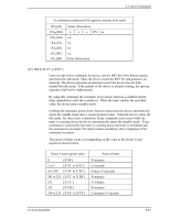
Interface (28) CHECK POWER MODE (X'98' or X'E5') The host checks the power mode of the device with this command. The host system can confirm the power save mode of the device by analyzing the contents of the Sector Count and Sector registers. The device sets the BSY bit and sets the following register value. After that, the device clears the BSY bit and generates an interrupt. Power save mode • During moving to standby mode • Standby mode • During returning from the standby mode • Idle mode • Active mode Sector Count register X'00' X'FF' X'FF' At command issuance (I/O registers setting contents) 1F7H(CM) 1F6H(DH) 1F5H(CH) 1F4H(CL) 1F3H(SN) 1F2H(SC) 1F1H(FR) X'98' or X'E5' xxx xx xx xx xx xx DV xx At command completion (I/O registers contents to be read) 1F7H(ST) 1F6H(DH) 1F5H(CH) 1F4H(CL) 1F3H(SN) 1F2H(SC) 1F1H(ER) Status information x x x DV xx xx xx xx X'00' ,X'80' or X'FF' Error information 5-62 C141-E104-03EN
-
 1
1 -
2
-
3
-
4
-
5
-
6
-
7
-
8
-
9
-
10
-
11
-
12
-
13
-
14
-
15
-
16
-
17
-
18
-
19
-
20
-
21
-
22
-
23
-
24
-
25
-
26
-
27
-
28
-
29
-
30
-
31
-
32
-
33
-
34
-
35
-
36
-
37
-
38
-
39
-
40
-
41
-
42
-
43
-
44
-
45
-
46
-
47
-
48
-
49
-
50
-
51
-
52
-
53
-
54
-
55
-
56
-
57
-
58
-
59
-
60
-
61
-
62
-
63
-
64
-
65
-
66
-
67
-
68
-
69
-
70
-
71
-
72
-
73
-
74
-
75
-
76
-
77
-
78
-
79
-
80
-
81
-
82
-
83
-
84
-
85
-
86
-
87
-
88
-
89
-
90
-
91
-
92
-
93
-
94
-
95
-
96
-
97
-
98
-
99
-
100
-
101
-
102
-
103
-
104
-
105
-
106
-
107
-
108
-
109
-
110
-
111
-
112
-
113
-
114
-
115
-
116
-
117
-
118
-
119
-
120
-
121
-
122
-
123
-
124
-
125
-
126
-
127
-
128
-
129
-
130
-
131
-
132
-
133
-
 134
134 -
 135
135 -
 136
136 -
 137
137 -
 138
138 -
 139
139 -
 140
140 -
 141
141 -
 142
142 -
 143
143 -
 144
144 -
145
-
146
-
147
-
148
-
149
-
150
-
151
-
152
-
153
-
154
-
155
-
156
-
157
-
158
-
159
-
160
-
161
-
162
-
163
-
164
-
165
-
166
-
167
-
168
-
169
-
170
-
171
-
172
-
173
-
174
-
175
-
176
-
177
-
178
-
179
-
180
-
181
-
182
-
183
-
184
-
185
-
186
-
187
-
188
-
189
-
190
-
191
-
192
-
193
-
194
-
195
-
196
-
197
-
198
-
199
-
200
-
201
-
202
-
203
-
204
-
205
-
206
-
207
-
208
-
209
-
210
-
211
-
212
-
213
-
214
-
215
-
216
-
217
-
218
-
219
-
220
-
221
-
222
-
223
-
224
-
225
-
226
-
227
-
228
-
229
-
230
-
231
-
232
 |
 |
