Fujitsu MHM2150AT Manual/User Guide - Page 34
Configuration of disk media heads, This system continuously circulates the air through
 |
View all Fujitsu MHM2150AT manuals
Add to My Manuals
Save this manual to your list of manuals |
Page 34 highlights
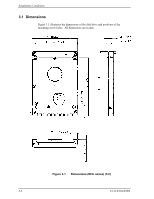
2.1 Device Configuration Head 5 4 3 2 1 0 Head 3 2 1 0 Head 3 2 1 0 Head 1 0 MHL2300AT MHM2200AT MHM2150AT (Either of head 0 or MHM2100AT head 3 is mounted.) Figure 2.2 Configuration of disk media heads (3) Spindle motor The disks are rotated by a direct drive Hall-less DC motor. (4) Actuator The actuator uses a revolving voice coil motor (VCM) structure which consumes low power and generates very little heat. The head assembly at the edge of the actuator arm is controlled and positioned by feedback of the servo information read by the read/write head. If the power is not on or if the spindle motor is stopped, the head assembly stays in the specific CSS zone on the disk and is fixed by a mechanical lock. (5) Air circulation system The disk enclosure (DE) is sealed to prevent dust and dirt from entering. The disk enclosure features a closed loop air circulation system that relies on the blower effect of the rotating disk. This system continuously circulates the air through the circulation filter to maintain the cleanliness of the air within the disk enclosure. (6) Read/write circuit The read/write circuit uses a LSI chip for the read/write preamplifier. It improves data reliability by preventing errors caused by external noise. (7) Controller circuit The controller circuit consists of an LSI chip to improve reliability. The highspeed microprocessor unit (MPU) achieves a high-performance AT controller. C141-E104-03EN 2-3
-
 1
1 -
2
-
3
-
4
-
5
-
6
-
7
-
8
-
9
-
10
-
11
-
12
-
13
-
14
-
15
-
16
-
17
-
18
-
19
-
20
-
21
-
22
-
23
-
24
-
25
-
26
-
27
-
28
-
 29
29 -
 30
30 -
 31
31 -
 32
32 -
 33
33 -
 34
34 -
 35
35 -
 36
36 -
 37
37 -
 38
38 -
 39
39 -
40
-
41
-
42
-
43
-
44
-
45
-
46
-
47
-
48
-
49
-
50
-
51
-
52
-
53
-
54
-
55
-
56
-
57
-
58
-
59
-
60
-
61
-
62
-
63
-
64
-
65
-
66
-
67
-
68
-
69
-
70
-
71
-
72
-
73
-
74
-
75
-
76
-
77
-
78
-
79
-
80
-
81
-
82
-
83
-
84
-
85
-
86
-
87
-
88
-
89
-
90
-
91
-
92
-
93
-
94
-
95
-
96
-
97
-
98
-
99
-
100
-
101
-
102
-
103
-
104
-
105
-
106
-
107
-
108
-
109
-
110
-
111
-
112
-
113
-
114
-
115
-
116
-
117
-
118
-
119
-
120
-
121
-
122
-
123
-
124
-
125
-
126
-
127
-
128
-
129
-
130
-
131
-
132
-
133
-
134
-
135
-
136
-
137
-
138
-
139
-
140
-
141
-
142
-
143
-
144
-
145
-
146
-
147
-
148
-
149
-
150
-
151
-
152
-
153
-
154
-
155
-
156
-
157
-
158
-
159
-
160
-
161
-
162
-
163
-
164
-
165
-
166
-
167
-
168
-
169
-
170
-
171
-
172
-
173
-
174
-
175
-
176
-
177
-
178
-
179
-
180
-
181
-
182
-
183
-
184
-
185
-
186
-
187
-
188
-
189
-
190
-
191
-
192
-
193
-
194
-
195
-
196
-
197
-
198
-
199
-
200
-
201
-
202
-
203
-
204
-
205
-
206
-
207
-
208
-
209
-
210
-
211
-
212
-
213
-
214
-
215
-
216
-
217
-
218
-
219
-
220
-
221
-
222
-
223
-
224
-
225
-
226
-
227
-
228
-
229
-
230
-
231
-
232
 |
 |
