Fujitsu MHM2150AT Manual/User Guide - Page 189
Table 5.18 Ultra DMA data burst timing requirements 2 of 2
 |
View all Fujitsu MHM2150AT manuals
Add to My Manuals
Save this manual to your list of manuals |
Page 189 highlights
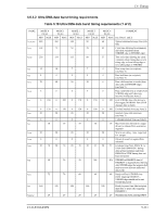
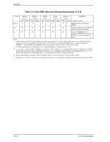
Interface Table 5.18 Ultra DMA data burst timing requirements (2 of 2) NAME MODE 0 (in ns) MODE 1 (in ns) MODE 2 (in ns) MODE 3 (in ns) MODE 4 (in ns) COMMENT MIN MAX MIN MAX MIN MAX MIN MAX MIN MAX (see Notes 1 and 2) tZIORDY 0 0 0 0 0 Minimum time before driving IORDY tACK 20 20 20 20 20 Setup and hold times for DMACK- (before assertion or negation) tSS 50 50 50 50 50 Time from STROBE edge to negation of DMARQ or assertion of STOP (when sender terminates a burst) Notes: 1) Unless otherwise specified, timing parameters shall be measured at the connector of the sender or receiver to which the parameter applies (see Note 5 for exceptions). For example, the sender shall stop generating STROBE edges tRFS after the negation of DMARDY-. Both STROBE and DMARDY- timing measurements are taken at the connector of the sender. 2) All timing measurement switching points (low to high and high to low) shall be taken at 1.5 V. 3) tUI, tMLI and tLI indicate sender-to-recipient or recipient-to-sender interlocks, i.e., one agent (either sender or recipient) is waiting for the other agent to respond with a signal before proceeding. tUI is an unlimited interlock that has no maximum time value. tMLI is a limited time-out that has a defined minimum. tLI is a limited time-out that has a defined maximum. 4) Special cabling shall be required in order to meet data setup (tDS) and data hold (tDH) times in modes 3 and 4. 5) Timing for tDVS and tDVH shall be met for all capacitive loads from 15 to 40 pf where all signals have the same capacitive load value. 5-112 C141-E104-03EN
-
 1
1 -
2
-
3
-
4
-
5
-
6
-
7
-
8
-
9
-
10
-
11
-
12
-
13
-
14
-
15
-
16
-
17
-
18
-
19
-
20
-
21
-
22
-
23
-
24
-
25
-
26
-
27
-
28
-
29
-
30
-
31
-
32
-
33
-
34
-
35
-
36
-
37
-
38
-
39
-
40
-
41
-
42
-
43
-
44
-
45
-
46
-
47
-
48
-
49
-
50
-
51
-
52
-
53
-
54
-
55
-
56
-
57
-
58
-
59
-
60
-
61
-
62
-
63
-
64
-
65
-
66
-
67
-
68
-
69
-
70
-
71
-
72
-
73
-
74
-
75
-
76
-
77
-
78
-
79
-
80
-
81
-
82
-
83
-
84
-
85
-
86
-
87
-
88
-
89
-
90
-
91
-
92
-
93
-
94
-
95
-
96
-
97
-
98
-
99
-
100
-
101
-
102
-
103
-
104
-
105
-
106
-
107
-
108
-
109
-
110
-
111
-
112
-
113
-
114
-
115
-
116
-
117
-
118
-
119
-
120
-
121
-
122
-
123
-
124
-
125
-
126
-
127
-
128
-
129
-
130
-
131
-
132
-
133
-
134
-
135
-
136
-
137
-
138
-
139
-
140
-
141
-
142
-
143
-
144
-
145
-
146
-
147
-
148
-
149
-
150
-
151
-
152
-
153
-
154
-
155
-
156
-
157
-
158
-
159
-
160
-
161
-
162
-
163
-
164
-
165
-
166
-
167
-
168
-
169
-
170
-
171
-
172
-
173
-
174
-
175
-
176
-
177
-
178
-
179
-
180
-
181
-
182
-
183
-
 184
184 -
 185
185 -
 186
186 -
 187
187 -
 188
188 -
 189
189 -
 190
190 -
 191
191 -
 192
192 -
 193
193 -
 194
194 -
195
-
196
-
197
-
198
-
199
-
200
-
201
-
202
-
203
-
204
-
205
-
206
-
207
-
208
-
209
-
210
-
211
-
212
-
213
-
214
-
215
-
216
-
217
-
218
-
219
-
220
-
221
-
222
-
223
-
224
-
225
-
226
-
227
-
228
-
229
-
230
-
231
-
232
 |
 |
