Fujitsu MHM2150AT Manual/User Guide - Page 149
Cylinder High register, Command Data 2 to 5
 |
View all Fujitsu MHM2150AT manuals
Add to My Manuals
Save this manual to your list of manuals |
Page 149 highlights
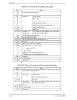
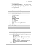
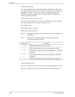
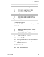
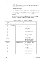
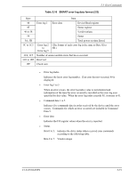
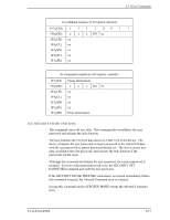
Interface • Check sum Two's complement of the lower byte, obtained by adding 511-byte data one byte at a time from the beginning. • Insurance failure threshold The limit of a varying attribute value. The host compares the attribute values with the thresholds to identify a failure. If an unrecoverable error is detected during execution of a command received by the device from the host computer, the device saves the SMART error log on the disk medium. The host computer can issue the SMART Read Log Sector sub-command (FR register = D5h, SN register = 01h) and read the SMART error log. Table 5.10 SMART error log data format (1/2) Byte 00 01 02 03 04 05 06 07 08 09 0A to 0D 0E to 3D 3E 3F 40 41 42 43 Item Error log version number Error log index Error log 1 Command Data 1 Device Control register Features register Sector Count register Sector Number register Cylinder Low register Cylinder High register Device/Head register Command register Elapsed time [ms] from the point when the power is turned on until command reception Command Data 2 to 5 (The format of each type of command data is the same as that of byte 02 to 0D.) Error data Reserved Error register Sector Count register Sector Number register Cylinder Low register Cylinder High register 5-72 C141-E104-03EN
-
 1
1 -
2
-
3
-
4
-
5
-
6
-
7
-
8
-
9
-
10
-
11
-
12
-
13
-
14
-
15
-
16
-
17
-
18
-
19
-
20
-
21
-
22
-
23
-
24
-
25
-
26
-
27
-
28
-
29
-
30
-
31
-
32
-
33
-
34
-
35
-
36
-
37
-
38
-
39
-
40
-
41
-
42
-
43
-
44
-
45
-
46
-
47
-
48
-
49
-
50
-
51
-
52
-
53
-
54
-
55
-
56
-
57
-
58
-
59
-
60
-
61
-
62
-
63
-
64
-
65
-
66
-
67
-
68
-
69
-
70
-
71
-
72
-
73
-
74
-
75
-
76
-
77
-
78
-
79
-
80
-
81
-
82
-
83
-
84
-
85
-
86
-
87
-
88
-
89
-
90
-
91
-
92
-
93
-
94
-
95
-
96
-
97
-
98
-
99
-
100
-
101
-
102
-
103
-
104
-
105
-
106
-
107
-
108
-
109
-
110
-
111
-
112
-
113
-
114
-
115
-
116
-
117
-
118
-
119
-
120
-
121
-
122
-
123
-
124
-
125
-
126
-
127
-
128
-
129
-
130
-
131
-
132
-
133
-
134
-
135
-
136
-
137
-
138
-
139
-
140
-
141
-
142
-
143
-
 144
144 -
 145
145 -
 146
146 -
 147
147 -
 148
148 -
 149
149 -
 150
150 -
 151
151 -
 152
152 -
 153
153 -
 154
154 -
155
-
156
-
157
-
158
-
159
-
160
-
161
-
162
-
163
-
164
-
165
-
166
-
167
-
168
-
169
-
170
-
171
-
172
-
173
-
174
-
175
-
176
-
177
-
178
-
179
-
180
-
181
-
182
-
183
-
184
-
185
-
186
-
187
-
188
-
189
-
190
-
191
-
192
-
193
-
194
-
195
-
196
-
197
-
198
-
199
-
200
-
201
-
202
-
203
-
204
-
205
-
206
-
207
-
208
-
209
-
210
-
211
-
212
-
213
-
214
-
215
-
216
-
217
-
218
-
219
-
220
-
221
-
222
-
223
-
224
-
225
-
226
-
227
-
228
-
229
-
230
-
231
-
232
 |
 |
