Fujitsu MHM2150AT Manual/User Guide - Page 101
At command issuance I/O registers setting contents, At command completion I/O registers contents
 |
View all Fujitsu MHM2150AT manuals
Add to My Manuals
Save this manual to your list of manuals |
Page 101 highlights
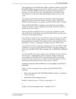
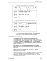
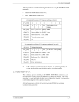
Interface If an error occurs during multiple sector write operation, the write operation is terminated at the sector where the error occurred. Command block registers contain the cylinder, the head, the sector addresses (in the CHS mode) or the logical block address (in the LBA mode) of the sector where the error occurred. Then the host can read the command block registers to determine what error has occurred and on which sector the error has occurred. At command issuance (I/O registers setting contents) 1F7H(CM) 0 0 1 1 0 0 0 R 1F6H(DH) x L x DV Start head No. /LBA [MSB] 1F5H(CH) 1F4H(CL) 1F3H(SN) 1F2H(SC) 1F1H(FR) Start cylinder No. [MSB] / LBA Start cylinder No. [LSB] / LBA Start sector No. / LBA [LSB] Transfer sector count xx At command completion (I/O registers contents to be read) 1F7H(ST) Status information 1F6H(DH) x L x DV End head No. /LBA [MSB] 1F5H(CH) 1F4H(CL) 1F3H(SN) 1F2H(SC) 1F1H(ER) End cylinder No. [MSB] / LBA End cylinder No. [LSB] / LBA End sector No. / LBA [LSB] 00 (*1) Error information *1 If the command is terminated due to an error, the remaining number of sectors of which data was not transferred is set in this register. 5-24 C141-E104-03EN
-
 1
1 -
2
-
3
-
4
-
5
-
6
-
7
-
8
-
9
-
10
-
11
-
12
-
13
-
14
-
15
-
16
-
17
-
18
-
19
-
20
-
21
-
22
-
23
-
24
-
25
-
26
-
27
-
28
-
29
-
30
-
31
-
32
-
33
-
34
-
35
-
36
-
37
-
38
-
39
-
40
-
41
-
42
-
43
-
44
-
45
-
46
-
47
-
48
-
49
-
50
-
51
-
52
-
53
-
54
-
55
-
56
-
57
-
58
-
59
-
60
-
61
-
62
-
63
-
64
-
65
-
66
-
67
-
68
-
69
-
70
-
71
-
72
-
73
-
74
-
75
-
76
-
77
-
78
-
79
-
80
-
81
-
82
-
83
-
84
-
85
-
86
-
87
-
88
-
89
-
90
-
91
-
92
-
93
-
94
-
95
-
 96
96 -
 97
97 -
 98
98 -
 99
99 -
 100
100 -
 101
101 -
 102
102 -
 103
103 -
 104
104 -
 105
105 -
 106
106 -
107
-
108
-
109
-
110
-
111
-
112
-
113
-
114
-
115
-
116
-
117
-
118
-
119
-
120
-
121
-
122
-
123
-
124
-
125
-
126
-
127
-
128
-
129
-
130
-
131
-
132
-
133
-
134
-
135
-
136
-
137
-
138
-
139
-
140
-
141
-
142
-
143
-
144
-
145
-
146
-
147
-
148
-
149
-
150
-
151
-
152
-
153
-
154
-
155
-
156
-
157
-
158
-
159
-
160
-
161
-
162
-
163
-
164
-
165
-
166
-
167
-
168
-
169
-
170
-
171
-
172
-
173
-
174
-
175
-
176
-
177
-
178
-
179
-
180
-
181
-
182
-
183
-
184
-
185
-
186
-
187
-
188
-
189
-
190
-
191
-
192
-
193
-
194
-
195
-
196
-
197
-
198
-
199
-
200
-
201
-
202
-
203
-
204
-
205
-
206
-
207
-
208
-
209
-
210
-
211
-
212
-
213
-
214
-
215
-
216
-
217
-
218
-
219
-
220
-
221
-
222
-
223
-
224
-
225
-
226
-
227
-
228
-
229
-
230
-
231
-
232
 |
 |
