Fujitsu MHM2150AT Manual/User Guide - Page 122
The READ MULTIPLE and WRITE MULTIPLE commands are, SET MAX FREEZE LOCK
 |
View all Fujitsu MHM2150AT manuals
Add to My Manuals
Save this manual to your list of manuals |
Page 122 highlights
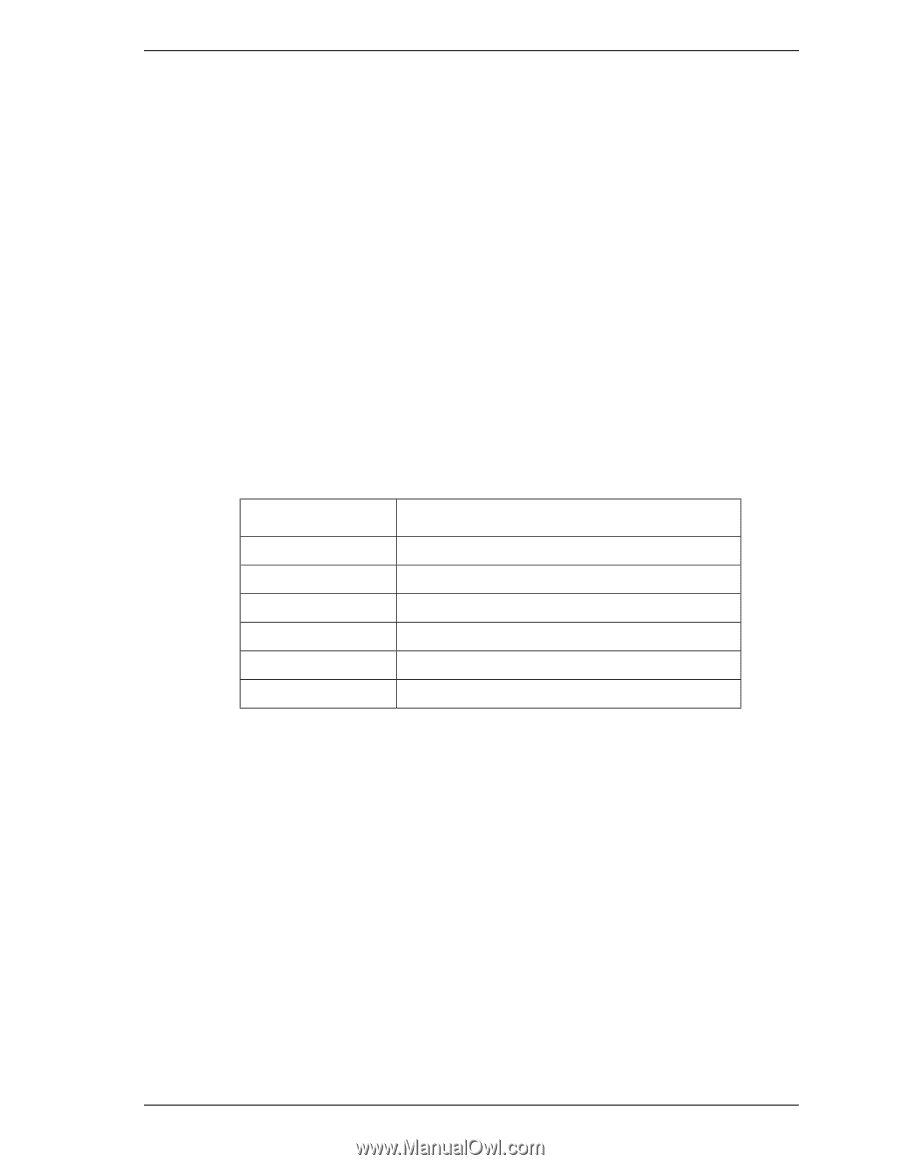
5.3 Host Commands Word 47 Bit 7-0 = 10: Word 59 = 0000: = 01xx: Maximum number of sectors that can be transferred per interrupt by the READ MULTIPLE and WRITE MULTIPLE commands. The READ MULTIPLE and WRITE MULTIPLE commands are disabled. The READ MULTIPLE and WRITE MULTIPLE commands are enabled. "xx" indicates the current setting for number of sectors that can be transferred per interrupt by the READ MULTIPLE and WRITE MULTIPLE commands. e.g. 0110 = Block count of 16 has been set by the SET MULTIPLE MODE command. (16) SET MAX (F9) Each SET MAX command is determined by the Features Register value. SET MAX Features Register Values Value 00h 01h 02h 03h 04h 05h - FFh Command Obsolete SET MAX SET PASSWORD SET MAX LOCK SET MAX UNLOCK SET MAX FREEZE LOCK Reserved • SET MAX ADDRESS This command allows the maximum address accessible by the user to be set in LBA or CHS mode. Upon receipt of the command, the device sets the BSY bit and saves the maximum address specified in the DH, CH, CL and SN registers. Then, it clears BSY and generates an interrupt. The new address information set by this command is reflected in Words 1, 54, 57, 58, 60 and 61 of IDENTIFY DEVICE information. If an attempt is made to perform a read or write operation for an address beyond the new address space, an ID Not Found error will result. When SC register bit 0, VV (Value Volatile), is 1, the value set by this command is held even after power on and the occurrence of a hard reset. When the VV bit is 0, the value set by this command becomes invalid when the power is turned on or a hard reset occurs, and the maximum address returns to the value (default value if not set) most lately set when VV bit = 1. C141-E104-03EN 5-45
-
 1
1 -
2
-
3
-
4
-
5
-
6
-
7
-
8
-
9
-
10
-
11
-
12
-
13
-
14
-
15
-
16
-
17
-
18
-
19
-
20
-
21
-
22
-
23
-
24
-
25
-
26
-
27
-
28
-
29
-
30
-
31
-
32
-
33
-
34
-
35
-
36
-
37
-
38
-
39
-
40
-
41
-
42
-
43
-
44
-
45
-
46
-
47
-
48
-
49
-
50
-
51
-
52
-
53
-
54
-
55
-
56
-
57
-
58
-
59
-
60
-
61
-
62
-
63
-
64
-
65
-
66
-
67
-
68
-
69
-
70
-
71
-
72
-
73
-
74
-
75
-
76
-
77
-
78
-
79
-
80
-
81
-
82
-
83
-
84
-
85
-
86
-
87
-
88
-
89
-
90
-
91
-
92
-
93
-
94
-
95
-
96
-
97
-
98
-
99
-
100
-
101
-
102
-
103
-
104
-
105
-
106
-
107
-
108
-
109
-
110
-
111
-
112
-
113
-
114
-
115
-
116
-
 117
117 -
 118
118 -
 119
119 -
 120
120 -
 121
121 -
 122
122 -
 123
123 -
 124
124 -
 125
125 -
 126
126 -
 127
127 -
128
-
129
-
130
-
131
-
132
-
133
-
134
-
135
-
136
-
137
-
138
-
139
-
140
-
141
-
142
-
143
-
144
-
145
-
146
-
147
-
148
-
149
-
150
-
151
-
152
-
153
-
154
-
155
-
156
-
157
-
158
-
159
-
160
-
161
-
162
-
163
-
164
-
165
-
166
-
167
-
168
-
169
-
170
-
171
-
172
-
173
-
174
-
175
-
176
-
177
-
178
-
179
-
180
-
181
-
182
-
183
-
184
-
185
-
186
-
187
-
188
-
189
-
190
-
191
-
192
-
193
-
194
-
195
-
196
-
197
-
198
-
199
-
200
-
201
-
202
-
203
-
204
-
205
-
206
-
207
-
208
-
209
-
210
-
211
-
212
-
213
-
214
-
215
-
216
-
217
-
218
-
219
-
220
-
221
-
222
-
223
-
224
-
225
-
226
-
227
-
228
-
229
-
230
-
231
-
232
 |
 |