GE AZ61H12DAB Owners Manual
GE AZ61H12DAB Manual
 |
View all GE AZ61H12DAB manuals
Add to My Manuals
Save this manual to your list of manuals |
GE AZ61H12DAB manual content summary:
- GE AZ61H12DAB | Owners Manual - Page 1
Instructions Electrical Connection .......... IB-16 Installing the Zoneline ......... 17, 18 Optional Drain Kit 19 Preparation 11 Replacing an Existing Unit? ........ 12 Troubleshooting Tips ...... 20, 21 Normal Operating Sounds ......... 22 Consumer Support Consumer Support - GE AZ61H12DAB | Owners Manual - Page 2
or loss of life. SAFETY PRECAUTIONS This Zoneline must be properly installed in accordance with the Installation Instructions before it is used. See the Installation Instructions in the back of this manual. Replace immediately all electric service cords that have become frayed or otherwise damaged - GE AZ61H12DAB | Owners Manual - Page 3
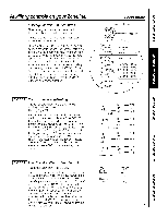
within 30 minutes, coil for service. Quick Heat Recovery Activateseach time thermostat set point is reached.On heat pump models,the heat pump operationwill resumeat the next call the heat setting 2-5 degrees will cause the Zoneline to use its electric heating elements in order to reach the new - GE AZ61H12DAB | Owners Manual - Page 4
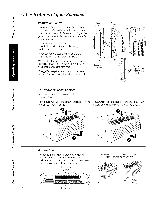
the vent door before use..Seethe Installation Instructions in the back of this manual. If you do not plan to use the ventilation feature, leave these two screws in place. The ventilation control lever is located at the middle left side of the Zoneline unit, behind the room cabinet. Open position - GE AZ61H12DAB | Owners Manual - Page 5
Auxiliary controls on your Zoneline. Auxiliary Controls--Aux Set Button The auxiliary set controls are located behind the room cabinet, below the control panel. Removethe room cabinet. See the To - GE AZ61H12DAB | Owners Manual - Page 6
Auxiliarg controls on gour Zoneline. I MODE31 Freeze Sentinel/Heat Sentinel Inthe default settingfor Node3, Heat Sentinelis off, Freeze Sentinelison. PressNODEuntila 3 appearsin the firstdigitqf the displayfor FreezeSentinelmode.TheCOOLLEDlighton the maincontrol will - GE AZ61H12DAB | Owners Manual - Page 7
[ MODE 8 All-Electric Heat (AZ6100 only) Thedefault settingfor Mode8 is OFF. Thiselectricheat optionfunctionsonly on the 6100 model.Whenthis optionis ON"n," tighten screwssecurely. A CAUTION: Improper wiring may damage the Zoneline electronics. No common busing is permitted. Damage or erratic - GE AZ61H12DAB | Owners Manual - Page 8
auxiliaryor externalfan can be controlledwith the indoorfan motor on the Zoneline. Connectionsprovide2/4V ACto energizea remoterelay, turningon the externalfan. Wall Thermostat. (Seethe installation instructions supplied with the remote thermostat and Hode instructions on page 7.) S" Class2 - GE AZ61H12DAB | Owners Manual - Page 9
clean, use water and a mild detergent. Do not use bleach or abrasives. Some commercial cleaners may damage the plastic parts. Outdoor Coils The coils on the outdoor side of the Zoneline should be checked regularly. If they are clogged with dirt or soot, they may be professionally steam cleaned. You - GE AZ61H12DAB | Owners Manual - Page 10
either the right or left side. To replace the air filters: Pushdown CAUTION:oonootperate the Zoneline without the filters in place. If a filter becomes torn or damaged, it should be are available from gour salesperson, GEdealer, GEService and Parts Center or authorized Customer Care® servicers. 10 - GE AZ61H12DAB | Owners Manual - Page 11
cord with this unit. Aluminum building wiring mag present special problems-consult a qualified electrician. When the unit is in the OFF position, there is still voltage to the electrical controls. Disconnect the power to the unit before servicing bg: 1 Removing the power cord (if it has one} from - GE AZ61H12DAB | Owners Manual - Page 12
holes in the unit side flonges for instollotion in woll coses other thon GE.To ovoid domoging the flonge insulotion, the instoller should use on owl or instolled before the unit is ploced in the woll cose.The instollotion instructions ore pocked with the kit. Duct kits available: RAK6052 RAK601/602 - GE AZ61H12DAB | Owners Manual - Page 13
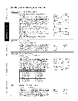
of the Zoneline and contact a qualified service technician. POWER Amp. LargeTandem 30 Amp. 230/208-voltreceptacleconfiguration. Branch Circuit and Unit Amperage Rating 15 20 30 Proper GE Power Cord with LCDI Device RAK5155 RAK3203 RAK3303* *Not approved for use on 7000 BTU models. ELECTRICAL - GE AZ61H12DAB | Owners Manual - Page 14
Instructions 265 VOLT ELECTRICAL CONNECTION OPTIONS WARNING: Connection of this 265 V AC product to a branch circuit MUSTbe done bg direct connection in accordance with the National ElectricalCode. Plugging this unit into a building-mounted exposed receptacle is not permitted bg code. These models - GE AZ61H12DAB | Owners Manual - Page 15
Installation Instructions MAKE ELECTRICAL CONNECTION TO THE UNIT m REMOVE JUNCTION BOX 1. Removethe junction box to the branch circuit ground wire. Make all wire connections bg using appropriate UL-listed electrical connectors and techniques (black to black, white to white and green to green). rsi - GE AZ61H12DAB | Owners Manual - Page 16
Installation Instructions POWER CONNECTION CHART 230/208 Volt Power Supply Kits with Current Leakage Detection Device RAK3203 RAK323503* I Power Cord Connections Wall Plug Configuration Perpendicular LarTgaenTdaenmdem I Circuit Protective Device 15-Amp Time-Delag Fuse or Breaker 20-Amp Time- - GE AZ61H12DAB | Owners Manual - Page 17
Instructions INSTALLING THE ZONELINE [] INSTALL THE WALL CASE AND EXTERIOR GRILLE The RAB71Aseries or RAB77A4wall case must be properlg installed per instructions room side following instructions packed with the grille. Insulated Wall Case This unit is designed to be installed in a GE plastic or an - GE AZ61H12DAB | Owners Manual - Page 18
Installation Instructions INSTALLING THE ZONELINE (cont.) [] INSTALL THE UNIT INTO THE WALL CASE Slide NOTE:There ore severol extro holes in the unit side flonges for instollotion in woll cosesother thon GE. To ovoid domoging the flonge insulotion,the instoller should use on owl or other shorp tool - GE AZ61H12DAB | Owners Manual - Page 19
Installation Instructions OPTIONAL--DRAIN KIT INSTALLATION Dry Air 25 Series models are designed to improve dehumidification by 25%. Since more moisture will be removed from the air, there is a greater possibilitg that water will drip from - GE AZ61H12DAB | Owners Manual - Page 20
service... Troubleshooting Tips Save time and mone_l! Review the charts on the following pages first and _lOUm%l not need to call for ervice. Problem Zoneline the filter at least every 30 days. See the Operating Instructions section. • When the Zoneline is first turned on you need to allow time for - GE AZ61H12DAB | Owners Manual - Page 21
GEAppliances.com Problem The air is not always cool or hot during operation The air does not feel worm enough during heating operation The unit is not blowing out air The electric heating feature does not work the unit. If the flashing light reappears within 30 minutes, call for service. 21 - GE AZ61H12DAB | Owners Manual - Page 22
may notice a few minutes delay in starting if you try to restart the Zoneline too soon after turning it off or if you adjust the thermostat right frost from the outdoor coil. After defrost, the unit will restart in electric heat to quickly warm the room to the desired comfort level. COMP_I_FSSO - GE AZ61H12DAB | Owners Manual - Page 23
part of the Zoneline which fails due to a defect in materials or workmanship. During this limited one-year warranty, GEwill also provide, free of charge, all labor and related service to replace the defective part. Ang part General. Warrantor: General Electric Company. Louisville, KY 40225 23 - GE AZ61H12DAB | Owners Manual - Page 24
at 800.626.2002 during normal business hours. Instructions contained in this manual coverprocedures to be performed by any user. Other servicing generally should be referred to qualified service personnel. Caution must be exercised,since improper servicing may cause unsafe operation. Contact Us - GE AZ61H12DAB | Owners Manual - Page 25
boTtier c6t_ chambre Filtre de ventilation Filtres 5 air Plateau Serpentin ext_rieur ....... 9 9 10 9 9 Instructions d'installation Branchement _lectrique 13-16 Installation de votre Zoneline ........ 17, 18 Preparation 11 Remise en place d'un appareil existant 12 Trousse de - GE AZ61H12DAB | Owners Manual - Page 26
et des blessures graves ou mortelles. MESURESDE SECURITE Vous devez bien installer votre Zoneline, conform@ment aux Instructions d'installation, avant de I'utiliser. Consultez les Instructions d'installation h I'arriere de ce manuel. Remplacez imm@diatement tout cordon d'alimentation abTm@ou - GE AZ61H12DAB | Owners Manual - Page 27
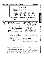
Les commandes de votre Zoneline. mHJGH _mCOOL mmFAN Er. E!.J --.,AUTOmmHEAT ! www.electromenagersge.c I TEMP FAN MODE SLEEP OPERATION COMMANDEDE FONCTIONNEMENTDU TEMPI RATURE VENTILATEURM, ODEETVEILLE Commandes O 0 Commande de temperature Lacommandede temperatureest utilis_epour o - GE AZ61H12DAB | Owners Manual - Page 28
Autres caract ristiques de votre Zoneline. Commande de ventilation NOTE: Vousdevez enleverde Io porte de ventilation deux vis d'exp_dition ovont d'utiliser votre opporeil. Consultezles Instructions d'instollotion 8 l'orri_re du present manual. Si vous envisogezde ne pos utiliser Io fonction de - GE AZ61H12DAB | Owners Manual - Page 29
Commandes auxiliaires sur votre Zoneline. www.electromenagersge.c Commandes auxiliaires--Bouton Aux Set Lescommandesauxiliairessontsitu_es6 I'arri@ede la carrosseriec6t_ chambre,en dessousdutableaude commande. Enlevelzacarrossercie6t_chambreC, onsultelazsection Enbvemendtelacarrossercie6t_chambre. - GE AZ61H12DAB | Owners Manual - Page 30
Commandes auxiliaires sur votre Zoneline. I MODE31 Gurde de gel/Gurde de chuleur Poulre r@glagpearddautduMode3,HeatSentinel(gardcehaleure) stinactiv@e, FreezSeentine(lgardegel)estactiv@e. AppuyeszurMODEjusqua'5pparitiodn'un3commepremiecrhiffreaffich_ pourobtenirlemodeGardeGelL. evoyant6LEDCOO( - GE AZ61H12DAB | Owners Manual - Page 31
www.electromenagersge.ca [ MODE 7 Mode canalisg Le r6glagepar ddaut pour le Mode7est OFF(d6sactiv6). Cer6glageest utilis6IorsqueI'appareilest instatl6avecune troussed'adaptateurde canalisation.Si I'appareilest canalis6, le ModeCanalis6doit @treactiv& Ceciaugmentela vitessedu ventilateurpour - GE AZ61H12DAB | Owners Manual - Page 32
marche ou arr_t_eparun commutateur situ_surlepanneau centradle commande. Une paire distinctde illdsoltalledre chaque commutateur de contr616e chaque Zoneline. I Il°l°J°l lI R_f@ez-vousau MODE 2 6 lapage 5 pourlesoptions de r_glagesdu ventilateur. h_ Commande centrale Thermostat _ distance - GE AZ61H12DAB | Owners Manual - Page 33
,il sera ndcessairede ddcrocher l'unitd du mur pour y acceder.Nettoblezle filtre deux lois par an ou choque lois que c'est ndcessoire. Mettez votre Zoneline en position OFF(orr_t)et ddbranchez-le avant de nettobler. Nettoyage du filtre de ventilation : IMPORTANT: Cefiltre ne peut _tre 6t& L'unit6 - GE AZ61H12DAB | Owners Manual - Page 34
6 gauche ou 6 droite. .4, MISE EN GARDE : Ne aites pas fonctionner votre Zoneline sans filtre en place. Si un filtre est d_chir_ ou endommag_, vous devez le remplacements sont disponibles chez votre vendeur,votre concessionnaire GE, tout centre de service et de pi@cesd@tach@eGs E ou tout centre de - GE AZ61H12DAB | Owners Manual - Page 35
6 I°installateur - Assurez-vous de laisser ° Pour votre s_curit_ personnelle, ce Zoneline doit ces instructions au consommateur. _tre bien mis 6 la terre. • Note au consommateur - Conservezces instructions pour r_f@ences futures. • L'installateur est responsable d'une bonne installation. • Toute - GE AZ61H12DAB | Owners Manual - Page 36
, RAK40,avec des grilles qui n'ont pas 6t@congues pour votre nouveau Zoneline GE.La trousse RAK40contient des ddlecteurs d'air et desjoints que vous pouvez monter sur avant de placer I'appareildans le battier mural. Les instructions d'installation sont contenues dans la trousse. Trousse d'adaptateur - GE AZ61H12DAB | Owners Manual - Page 37
Instructions d'installation S OPTIONSDE BRANCHEMENTELECTRIQUEDE 230/208 VOLTS pas enfonc6, cessez d'utiliser votre Zoneline et appelez un technicien de service qualifi6. BRANCHEMENT DE CORDON D'ALIMENTATION en amp@res du circuit de d_rivation et de I'appareil 15 Bon cordon d'alimentation GE avec - GE AZ61H12DAB | Owners Manual - Page 38
une enceinte flexible _our branchement direct. Intensit_ en amp@res du circuff de d6rivation et de I'appareil 15 GE 6lectrique RAK204E15 RAK5172 RAK204E20 RAK5202 RAK204E30 RAK5302* *Non approuv_ pour utilisation sur les modules de 7000 BTU. Vous devez suivre soigneusement les instructions - GE AZ61H12DAB | Owners Manual - Page 39
Instructions d'installation BRANCHEMENT ELECTRIQUE DE L'APPAREIL iTI ENLEVEZ LA BO/TE DE DI_RIVATION 1 Enlevezle couvercle de la boTtede d@rivationen enlevant les deux vis de devant. 2 Enlevezla - GE AZ61H12DAB | Owners Manual - Page 40
Instructions d'installation TABLEAU DE CONTACT ELECTRIQUE Bronchements de cordon d' protection de circuit I Fusible d@loi/disjoncteur de 15 omp Fusible d@loi/disjoncteur de 20 amp Fusible d@lai/disjoncteur de 30 amp Puissance du chauffage @230/208 Volts 2,55 KW/2,09 KW 3,45 KW/2,82 KW - GE AZ61H12DAB | Owners Manual - Page 41
d'installation INSTALLATION DU ZONELINE [] INSTALLATION DU BO/TIER MURAL ET DE LA GRILLE EXTI_RIEURE Vous devez bien installer le boTtiermural RAB77A4ou la s@rieRAB71A,conform@mentoux instructions comprises dons le boTtier. • Enlevezle renfort en carton et le ponneou protecteur ext@rieurU - GE AZ61H12DAB | Owners Manual - Page 42
Instructions d'installation INSTALLATION DU ZONELINE (suite) I-_ INSTALLATION DE L'APPAREIL DANS LE BOTTLER MURAL Faitesglisser I'appareil dans le boTtiermural et fixez avec quatre visen lesfaisant passer par les trous de la - GE AZ61H12DAB | Owners Manual - Page 43
int_rieur des murs ext_rieurs du batiment, nous vous recommandons d'utiliser une trousse de drainage RAD10. Drainage ext_rieur Consultez les instructions d'instollotion dans la trousse RADIO. © Tubealternatifen cuivre de6 pode long,et de 1/2 pode diam_treext6rieur Tuyaudedrainagede 1/2 po • _-_i - GE AZ61H12DAB | Owners Manual - Page 44
de I'air ext_rieur est r_duite ou I'air recircule. • Assurez-vousqu'il n'y ait pas de rideau, de tenture ou de meuble qui bloque I'avant du Zoneline. • Assurez-vousque la grille d'air ne soit pas bouch@e. Cela peut faire arr@terI'appareil5 cause du protecteur de surcharge du compresseur. La grille - GE AZ61H12DAB | Owners Manual - Page 45
www.electromenagersge.ca Probl_me Odeur de brOl_ au d_butdes operations de r_chauffement Causes Possibles II g a de la poussi_re sur I'_l_ment de chauffage, Correctifs • Cela peut occasionner une odeur de brOl_ au d_but des operations de r_chauffement. Cette odeur doit disparaTtre rapidement. L' - GE AZ61H12DAB | Owners Manual - Page 46
de ventilateur quand il s'arr@teet se met en marche. Vous pouvez noter un d@ladi e quelques minutes quand vous essagez de remettre en marche votre Zoneline trop t6t apr@sI'avoir arr@t@ou si vous ajustez le thermostatjuste apr_s I'arr@dt u compresseur. C'est dO @un m@canismeint@gr@de protection du - GE AZ61H12DAB | Owners Manual - Page 47
GE remplacera gratuitement : Toute pigce du Zoneline pr_sentant un d_faut dO au materi_l ou _ Io main-d'oeuvre. Au cours de cette garantie limit_e d'un an, GE couvrira gratuitement les frais de main d'oeuvre et de service des consommoteurs. Garant : General Electric Compang. Louisville, KY 40225 23 - GE AZ61H12DAB | Owners Manual - Page 48
-nous par l SIntietrenet Wau esibte [email protected]/o4hmeu@resnpaarjgouer,rstousGlesEjourswdewI'[email protected] Servicede r@parations Service de r@parationsGEest tout pr@sde vous. Pour faire r@parervotre @lectrom@nageGr E,il suffit de nous t_l@phoner. 1.800 - GE AZ61H12DAB | Owners Manual - Page 49
externas 9 9 10 ....... 9 9 Instrucciones de instalaci6n Conexi6n el_ctrica _LDesea cambiar una unidad ga instalada Instalaci6n del acondicionador de aire Zoneline Kit de drenaje opcional Preparaci6n 13-16 12 17, 18 19 11 Solucionar problemas .......... 20, 21 Sonidos normales de - GE AZ61H12DAB | Owners Manual - Page 50
abrasi6n en su superficie en alguno de sus extremos. Desenchufe o desconecte el Zoneline desde la caja de fusibles o el disguntor antes de realizar cualquier tipo Para m6s detalles, ver las Instrucciones de instalaci6n en este manual. NOTA" Recomendamos en@gicamente que cualquier servicio Ilevado a - GE AZ61H12DAB | Owners Manual - Page 51
Sobrelos controles del Zoneline. ! HiGH ===,COOL LOW _=, FAN AUTO HEAT m ! TEMP FAN MODE SLEEPOPERATION CONTROLDE OPERACIONDEVENTILADOR, TEMPERATURA Controles MODOY SUSPENSION O 0 Control de temperatura Elcontrodletemperatusreausaparamantenerla temperatuarmabienteE.lcompresosreencender6 g - GE AZ61H12DAB | Owners Manual - Page 52
manual. Si usted no planea utilizar la corocteEstica de ventilacidn, deje estos dos tomillos en su lugar. Lo palonco de control de ventiloci6n se encuentra sabre el lade izquierdo media de Io unidad Zoneline riel superior (1).Presionehacia adentro desde la parte inferior haste qua encaje en su lugar - GE AZ61H12DAB | Owners Manual - Page 53
Controles auxiliares del Zoneline. 6EAppliances.com Controles auxiliares--Bot6n de configuraciones Los controles de configuraciones auxiliares se encuentran detrGs del gabinete del ambiente, debajo del panel de control. Retire - GE AZ61H12DAB | Owners Manual - Page 54
Controles auxiliares del Zoneline. I MODE31 Monitor de congelaci6n/Monitor de calor EnlaconfiguraciGpnredeterminadpaaraelHodo3,HeatSentine(lmonitodr e HIGH(atta) / COOL(frio) calor)seencuentrdaesactivadpoeroFreezSeentine(lmonitodrecongelaciGn) seencuentraactivado. --'_ L{ ---- LAOUWT(Ob( - GE AZ61H12DAB | Owners Manual - Page 55
Ouiteeltornillodelatapadeacceso. r-4-1Pinaferarhioadrceelracostneermxiionnaeleeslys#acjturisctaebsini,esnelrotselotosmcailbloles.senla parte r-5--Da1ceoslpouc&adlrsaertaepaalidzaetraocdcaesslaoysceolgnaebxiinoenteeddseeslaemabdiaesvn,utee.lva Elpropietarieosresponsabdleerealizatrodaslasconexioneys - GE AZ61H12DAB | Owners Manual - Page 56
en forma local) Una vezque se Io conecta, un ventilador au×iliar o externo puede controlarse con el motor de ventilaci6n interno de Zoneline. Las conexiones brindan 2a voltios de CA para suministrar energ[a a un circuito intermedio, Io que enciende el ventilador externo. I lq : LiJJf Ventilador - GE AZ61H12DAB | Owners Manual - Page 57
un detergente suave. No utilice blanqueador o sustancias abrasivas. Algunos limpiadores comerciales pueden da_ar las partes pl6sticas. Serpentinas externas Las serpentinas de la zona externa del Zoneline deben verificarse de manera regular.Si est6n tapadas con suciedad u hollfn, un experto puede - GE AZ61H12DAB | Owners Manual - Page 58
que puede hacer para mantener en buen estado su Zoneline es limpiar el filtro par Io menos cada 30 importante. • Haga fluir agua a trav@sde los flltros desde la parte trasera. • Seque bien antes de volver a colocar. NOTA:Losfiltros de GE,el Centro de Reparaci6n g Piezasde GE o centro autorizado de - GE AZ61H12DAB | Owners Manual - Page 59
Instrucciones de instalaci6n Acondicionador de aire Zoneline Preguntas? Llame al 1.800.GE.CARES o visite nuestro sitio en la red a: National Electrical Code (C6digo de Electricidad Nacional)(NEC) o los c6digos u ordenanzas locales. • Pare su seguridad personal, el acondicionador de aire Zoneline - GE AZ61H12DAB | Owners Manual - Page 60
correctamente o se romper6 en forma prematura. Un kit deflector, RAK40,puede utilizarse con parrillas que no fueron dise_adas para las nuevos acondicionadores Zoneline de GE.El RAK40contiene deflectores de aire Ujuntas que se colocan sobre la unidad, a fin de enviar la salida de aire caliente en una - GE AZ61H12DAB | Owners Manual - Page 61
RESETno queda enganchado, deje de utilizar el acondicionador de aire Zoneline g comuniquese con un t_cnico calificado. CONEXION DE CABLE DE Clusificuci6n de circuito derivudo y umperuje de lu unidud 15 Cuble de energiu GE con dispositivo LCDI RAK3153 20 RAK3203 30 RAK3303* *No se ha aprobado - GE AZ61H12DAB | Owners Manual - Page 62
caja externa. Estos modelos deben instalarse utilizando el kit de GE de suministro de energia adecuado para el amperaje de circuito derivado de circuito derivado g amperaje de la unidad Kit adecuado de sub-base GE Kit de suministro de energia 15 RAK204E15 RAK5172 20 RAK204E20 RAK5202 30 - GE AZ61H12DAB | Owners Manual - Page 63
caja de conexiones, encaje las pestanas izquierdas en la cara derecha inferior en la unidad, alineando los orificios de los tornillos en la parte superior e inferior, y atornille los dos tornillos hasta que el sistema quede asegurado. AsegOresede que todos los cables hayan quedado dentro de la caja - GE AZ61H12DAB | Owners Manual - Page 64
T(indem grande Dispositivo de protecci6n de circuito Fusible de tiempo retardado/ disyuntor de 15 amp Fusible de tiempo retardado/ disyuntor de 20 amp Fusible de tiempo retardado/ disyuntor de 30 amp Conexiones directa Kits para suministro de energia de 230/208 voltios RAK4157 RAK4207 RAK4307 - GE AZ61H12DAB | Owners Manual - Page 65
Instrucciones de instalaci6n COMO INSTALAR EL ZONELINE [] INSTALACION DEL MONTANTE DE PARED Y LA PARRILLA para instalarse con un montante pldstico de GE o un montante de pared de metal aislante. Estoselementos minimizan la formaci6n de condensaci6n en la parte que da a la habitaci6n. Los montantes - GE AZ61H12DAB | Owners Manual - Page 66
Instrucciones de instalaci6n COMO INSTALAR EL ZONELINE (cont.) [] C6MO INSTALAR LA UNIDAD EN EL MONTANTE DE PARED Deslicela los rebordes laterales de la unidad para instalaci6n en montantes de pared diferentes o GE.Poro evitor donor el oislomiento del reborde, el instalador deber6 usar un punz6n u - GE AZ61H12DAB | Owners Manual - Page 67
Instrucciones de instalaci6n 0 OPCIONAL: INSTALACION DE UN KIT DE DRENAJE Los modelos de la serie Drg Air 25 est6n dise6ados para mejorar la dehumidificaci6n en un 25%. Puesto que se absorber6 m6s humedad del aire, existe una mayor posibilidad de goteo de agua desde la unidad que con un - GE AZ61H12DAB | Owners Manual - Page 68
par Io menos cada 30 dfas. Ver la secci6n Instrucciones de opemci6n. La habitaci6n estaba mug fria • Cuando reci@nse enciende, Zoneline necesita un tiempo o mug caliente, prudencial para enfriar a calentar una habitaci6n. Est6 ingresando aire exterior a la habitaci6n. • Configure el control de - GE AZ61H12DAB | Owners Manual - Page 69
GEApplionces.com Problema Olora quemado en el comienzo de la operociSn de colefocci6n El aire no siempre est6 fresco o caliente durante la operaci6n El aire no se siente Io suficientemente caliente durante la operaciSn de calefacciSn La unidad no emite aire La calefacci6n eMctrica no funciona El - GE AZ61H12DAB | Owners Manual - Page 70
cgcle. Estoprovocar6 que el ventilador se encienda g apague junto al compresor.Tambi@npuede escucharse un ventilador que se enciende g apaga. Notar6 que Zoneline demora unos minutos en volver a encenderse si se trata de reanudar el funcionamiento demasiado r6pido despu@sde apagarlo o si se ajusta el - GE AZ61H12DAB | Owners Manual - Page 71
arras derechosque voriardn de estado o estado.Paro sober cudles son sus derechos legales,consulte o la oficina de osuntos del consumidor local o la oficina del Attomeg General en su Iocolidad. Garante: General Electric Company. Louisville, KY40225 23 - GE AZ61H12DAB | Owners Manual - Page 72
que vengan a realizar una reparaci6n. Solicite una reparaci6n GEAppliances.com El servicio de expertos GE est6 a tan s61oun paso de su puerta, jEntre en Ifnea g solicite su este manual cubren los procedimientos a seguir por cualquier usuario. Cualquier otra reparaci6n deberia, por regla general,
-
 1
1 -
 2
2 -
 3
3 -
 4
4 -
 5
5 -
 6
6 -
 7
7 -
8
-
9
-
10
-
11
-
12
-
13
-
14
-
15
-
16
-
17
-
18
-
19
-
20
-
21
-
22
-
23
-
24
-
25
-
26
-
27
-
28
-
29
-
30
-
31
-
32
-
33
-
34
-
35
-
36
-
37
-
38
-
39
-
40
-
41
-
42
-
43
-
44
-
45
-
46
-
47
-
48
-
49
-
50
-
51
-
52
-
53
-
54
-
55
-
56
-
57
-
58
-
59
-
60
-
61
-
62
-
63
-
64
-
65
-
66
-
67
-
68
-
69
-
70
-
71
-
72
 |
 |
GEAppliances.com
Q
QJ
0
N
0
0_
0_
Safety
Instructions
.............
2
Operating
Instructions
Air Direction
........................
4
Auxiliary
Controls
................
5-8
Controls
...........................
3
To Remove
the Room Cabinet
......
/4
Ventilation
Control
.................
/4
Care
and
Cleaning
Air Filters
.........................
10
Base Pan
..........................
9
Outdoor
Coils
......................
9
Room Cabinet
and Case
............
9
Ventilation
Filter
....................
9
Installation
Instructions
Electrical
Connection
..........
IB-16
Installing
the Zoneline
.........
17, 18
Optional
Drain
Kit
.................
19
Preparation
.......................
11
Replacing
an Existing Unit?
........
12
Troubleshooting
Tips
......
20, 21
Normal
Operating
Sounds
.........
22
Consumer
Support
Consumer
Support
........
Back Cover
Warranty
.........................
2:3
Heat/Cool
Model
4100
Heat
Pump
Model
6100
EspaSol
For a Spanish
version
of this
manual,
visit our Website
at
www.zoneline.com/literature.
Para consultar
una version
en espaflol
de este manual
de instrucciones,
visite
nuestro
sitio de internet
www.zoneline.com/literature.
Frangais
For a French version
of this
manual,
visit our Website
at
www.zoneline.com/literature.
Pour un version
franqais
de
ce manuel
d'utilisation,
veuillez
visiter
notre site web
6 I'adresse
www.zoneline.com/literature.
0_
Write the model and
serial
numbers here:
Model
#
Serial
#
Find these numbers on a label
behind the room cabinet on the
base pan.
TINSEA576JBRZ
49-7612
04-09
JR