GE AZ61H12DAB Owners Manual - Page 7
Caution
 |
View all GE AZ61H12DAB manuals
Add to My Manuals
Save this manual to your list of manuals |
Page 7 highlights
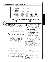
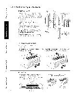
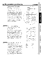
I [ MODE 7 Duct Mode Thedefault settingfor Mode7 is OFF. Thissetting isusedwhenthe unit is installedusinga duct adapter kit. If the unit isducted,the DuctNode needsto be set to ON.Thisincreasesthe fan speedto ensurepropercirculation. PressMODEuntil a 7 appearsin the first digit of the display.Pressthe up or down arrow keysto set this switchto OFF"u" or ON"n ."This isshown in the seconddigit of the display.PressAUXSETtoconfirm your selectionand exit AUXSETmode. GEAppliances.com ForModelAZ6100,pressMODEto continuesetting other functions.PressingMODEon ModelAZ4100will returnyou to AUXSETmodeand an "AU"will appearin the display. t7 lU DuctModeOFF F'IF I DuctModeON [ MODE 8 All-Electric Heat (AZ6100 only) Thedefault settingfor Mode8 is OFF. Thiselectricheat optionfunctionsonly on the 6100 model.Whenthis optionis ON"n," heat pump operationislockedout, causingthe unitto provide only electricresistanceheat. Toset All-ElectricHeat option,press MODE until an 8 appears in the first digit of the display. Pressthe up or downarrow keysto set this switchto OFF"u" or ON"n." Thisisshownin theseconddigit ofthe display. PressAUXSETtoconfirmgour selectionandexitAUXSET mode,or pressMODEtocontinuesettingotherfunctions. EtU AII-Ele_'trk" HeatOFF on AII-Ele_'trk" HeatON [ MODE 9 Heat Boost (AZ6100 only) Thedefaultsettingfor Hode9 isOFF. WhenHeat Boost isONand outertemperaturesare between25°Fand/46%heatpumponlg operationis lockedout. Thissettingis usedto providesupplementarg heatto the heatpumpoperationbg electricresistance heatin conditionswherethe heat pump-onlgoperation is notsufficientto maintaina consistent,comfortable roomtemperature.NOTET: emperatureBoostoption shouldnot be usedwith remotethermostatoperation. Thiswill causethe unitto switchto resistanceheatwhen the outdoortemperatureis/46%. Toset Heat Boost,pressMODEuntil a 9 appearsin the first digitof the displag.Pressthe up or down arrowkegs to set this switchto OFF"u" or ON"l-I ."Thisisshown in theseconddigitof the display.PressAUXSETto confirmgour selectionand exitAUXSETmode. HeatBoostOFF HeatBoosOt N Auxiliary Controls--Terminal Connections Theauxiliarycontrolsare locatedbehindthe room cabinetbeneaththe accesscover. Theowneris responsiblefor makingall connectionsand settingthe appropriateAUXSETmode. E_] Turnoff and unplugthe unit. [] Removethe roomcabinet.Seethe ToRemovethe RoomCobinetsection. [_] Removethe screwfrom the accesscover. [_]To makewiringconnectionsi,nsertthe wiresintothe bottomof the terminalsand tighten screwssecurely. A CAUTION: Improper wiring may damage the Zoneline electronics. No common busing is permitted. Damage or erratic operation may result. A separate wire pair must be run from each separate controlling switch to each individual Zoneline. r_ Afterall desiredconnectionshavebeenmade, replacethe accesscoverand roomcabinet. ExternalFan CentralDeskControl o >< o z,,< z,,< z oo o° I LCommon _ hite - Heater Yellow- Compressor Black- Solenoid(AZ61only) Green- HighSpeed Fan Green- Low SpeedFan 7 Red- 24 V AConly
-
 1
1 -
 2
2 -
 3
3 -
 4
4 -
 5
5 -
 6
6 -
 7
7 -
 8
8 -
 9
9 -
 10
10 -
 11
11 -
 12
12 -
13
-
14
-
15
-
16
-
17
-
18
-
19
-
20
-
21
-
22
-
23
-
24
-
25
-
26
-
27
-
28
-
29
-
30
-
31
-
32
-
33
-
34
-
35
-
36
-
37
-
38
-
39
-
40
-
41
-
42
-
43
-
44
-
45
-
46
-
47
-
48
-
49
-
50
-
51
-
52
-
53
-
54
-
55
-
56
-
57
-
58
-
59
-
60
-
61
-
62
-
63
-
64
-
65
-
66
-
67
-
68
-
69
-
70
-
71
-
72
 |
 |
