HP 6125G HP 6125G & 6125G/XG Blade Switches Installation Guide-6W100
HP 6125G Manual
 |
View all HP 6125G manuals
Add to My Manuals
Save this manual to your list of manuals |
HP 6125G manual content summary:
- HP 6125G | HP 6125G & 6125G/XG Blade Switches Installation Guide-6W100 - Page 1
HP 6125 Blade Switch Series Installation Guide Part number: 5998-3151 Document version: 6W100-20120907 - HP 6125G | HP 6125G & 6125G/XG Blade Switches Installation Guide-6W100 - Page 2
, or use of this material. The only warranties for HP products and services are set forth in the express warranty statements accompanying such products and services. Nothing herein should be construed as constituting an additional warranty. HP shall not be liable for technical or editorial errors or - HP 6125G | HP 6125G & 6125G/XG Blade Switches Installation Guide-6W100 - Page 3
Garbled terminal display 18 Configuration problems 19 Software upgrade failure 19 Password loss 19 Login password loss 19 BootWare password loss 20 Super password loss 20 Hardware failures 21 Interface failure 21 Support and other resources 22 Contacting HP 22 Subscription service 22 i - HP 6125G | HP 6125G & 6125G/XG Blade Switches Installation Guide-6W100 - Page 4
information 22 Documents 22 Websites 22 Conventions 23 Appendix A Technical specifications 25 Appendix B Ports and LEDs 26 Ports 26 Console port 26 10/100/1000Base-T Ethernet port 26 IRF/SFP port and SFP port 26 SFP+ port 27 LEDs 29 Unit ID LED 29 Health LED 29 10/100/1000Base - HP 6125G | HP 6125G & 6125G/XG Blade Switches Installation Guide-6W100 - Page 5
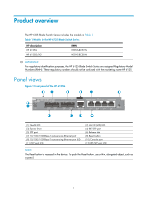
Product overview The HP 6125 Blade Switch Series includes the models in Table 1: Table 1 Models in the HP 6125 Blade Switch Series HP description HP 6125G HP 6125G/XG RMN HSTNS-BC57-N HSTNS-BC58-N IMPORTANT: For regulatory identification purposes, the HP 6125 Blade Switch Series are assigned - HP 6125G | HP 6125G & 6125G/XG Blade Switches Installation Guide-6W100 - Page 6
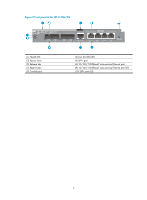
Figure 2 Front panel of the HP 6125G/XG (1) Health LED (3) Ejector lever (5) Release tab (7) Reset button (9) Console port (2) Unit ID (UID) LED (4) SFP+ port (6) 10/100/1000Base-T auto-sensing Ethernet port (8) 10/100/1000Base-T auto-sensing Ethernet port LED (10) SFP+ port LED 2 - HP 6125G | HP 6125G & 6125G/XG Blade Switches Installation Guide-6W100 - Page 7
. • Identify the interconnect bay to install the blade switch. For more information, see HP BladeSystem Enclosure Setup and Installation Guide. Installing and removing the blade switch IMPORTANT: • If the blade switch does not install easily, make sure that it is correctly oriented. • To prevent - HP 6125G | HP 6125G & 6125G/XG Blade Switches Installation Guide-6W100 - Page 8
into the interconnect bay 7. Verify that the Health LED is green after the blade switch starts up. Otherwise, check the installation. 8. Choose proper cables for the blade switch. For more information about ports, see "Ports." For more information about cable installation, see "Connecting the - HP 6125G | HP 6125G & 6125G/XG Blade Switches Installation Guide-6W100 - Page 9
to connect the 10/100/1000Base-T ports on your blade switch to the network. These ports use RJ-45 connectors and support MDI/MDI-X auto-sensing. To connect a 10/ SFP+][XFP] Transceiver Modules Installation Guide. To install a transceiver module into the port on the blade switch and the peer device: - HP 6125G | HP 6125G & 6125G/XG Blade Switches Installation Guide-6W100 - Page 10
to connect transceiver modules LC plug SFP module Testing connectivity After you connect the blade switch to the network, use the ping or tracert command to test network connectivity. For more information about these two commands, see HP 6125 Blade Switch Series Network Management and Monitoring - HP 6125G | HP 6125G & 6125G/XG Blade Switches Installation Guide-6W100 - Page 11
the other end for connecting to the serial port on the console terminal. Figure 6 Console cable Setting up the configuration environment To connect a terminal, for example, a PC, to the blade switch: 1. Plug the DB-9 female connector of the console cable to the serial port of the PC. 2. Plug the RJ - HP 6125G | HP 6125G & 6125G/XG Blade Switches Installation Guide-6W100 - Page 12
Setting terminal parameters To configure and manage the blade switch, you must run a terminal emulator program on the console terminal, for example, a PC. This section uses Windows XP HyperTerminal as an example. The following are - HP 6125G | HP 6125G & 6125G/XG Blade Switches Installation Guide-6W100 - Page 13
Figure 9 Setting the serial port used by the HyperTerminal connection 4. Set Bits per second to 9600, Data bits to 8, Parity to None, Stop bits to 1, and Flow control to None, and click OK. Figure 10 Setting the serial port parameters 5. Select File > Properties in the HyperTerminal window. 9 - HP 6125G | HP 6125G & 6125G/XG Blade Switches Installation Guide-6W100 - Page 14
Figure 11 HyperTerminal window 6. On the Settings tab, set the emulation to VT100, and click OK. Figure 12 Setting terminal emulation in Switch Properties dialog box 10 - HP 6125G | HP 6125G & 6125G/XG Blade Switches Installation Guide-6W100 - Page 15
methods available for a VTY user interface. For more information about login authentication methods, see HP 6125 Blade Switch Series Fundamentals Configuration Guide. Table 2 Telnet login authentication methods Authentication method None Password Characteristics Application scenarios Easy to - HP 6125G | HP 6125G & 6125G/XG Blade Switches Installation Guide-6W100 - Page 16
see HP 6125 Blade Switch Series Configuration Guides. Configuration example Configuring Telnet # Enter system view. system-view # Enable the Telnet server. [Sysname] telnet server enable # Enter the user interface view VTY 0. [Sysname] user-interface vty 0 # Enable password authentication - HP 6125G | HP 6125G & 6125G/XG Blade Switches Installation Guide-6W100 - Page 17
# Assign GigabitEthernet 1/1/5 to VLAN 10. [Sysname-vlan10] port gigabitethernet 1/1/5 [Sysname-vlan10] quit 13 - HP 6125G | HP 6125G & 6125G/XG Blade Switches Installation Guide-6W100 - Page 18
, see HP 6125 Blade Switch Series IRF Configuration Guide. Determine which switch you want to use as the master for managing all member switches in the IRF fabric. An IRF fabric has only one master switch. You configure and manage all member switches in the IRF fabric at the command line interface - HP 6125G | HP 6125G & 6125G/XG Blade Switches Installation Guide-6W100 - Page 19
topologies for an IRF fabric made up of HP 6125G blade switches for IRF connections. • The IRF port connections in the two figures are for illustration only, and more connection methods are available. • Any or all of the four SFP+ ports on the 6125G/XG can be used either for IRF or data connections - HP 6125G | HP 6125G & 6125G/XG Blade Switches Installation Guide-6W100 - Page 20
from the network management station. (See HP 6125 Blade Switch Series Fundamentals Configuration Guide.) 4. Check that you can manage all member switches as if they were one node. 5. Display the running status of the IRF fabric by using the commands in Table 4. Table 4 Displaying and maintaining - HP 6125G | HP 6125G & 6125G/XG Blade Switches Installation Guide-6W100 - Page 21
: To avoid IP address collision and network problems, configure at least one multi-active detection (MAD) mechanism to detect the presence of multiple identical IRF fabrics and handle collisions. For more information about MAD detection, see HP 6125 Blade Switch Series IRF Configuration Guide. 17 - HP 6125G | HP 6125G & 6125G/XG Blade Switches Installation Guide-6W100 - Page 22
Enclosure Setup and Installation Guide. NOTE: If you cannot locate failures by following the guidelines in this chapter, contact HP Support. Software failures If the configuration environment setup is correct, the configuration terminal displays boot information when the blade switch is powered on - HP 6125G | HP 6125G & 6125G/XG Blade Switches Installation Guide-6W100 - Page 23
When you detect configuration errors, re-configure the blade switch or restore the factory settings for the blade switch. For more information about commands and configurations, see HP 6125 Blade Switch Series Configuration Guides and HP 6125 Blade Switch Series Command References. Software upgrade - HP 6125G | HP 6125G & 6125G/XG Blade Switches Installation Guide-6W100 - Page 24
, the blade switch runs with the initial configuration. To restore to the saved configuration, use the display saved-configuration command to display the configuration, and then copy and execute the configuration. BootWare password loss If you forget the BootWare password, contact HP Support. To - HP 6125G | HP 6125G & 6125G/XG Blade Switches Installation Guide-6W100 - Page 25
HP Support. Interface failure If the LED of an interface connected to the network is off, the interface or the connecting cable may fail. To troubleshoot the interface: 1. Verify that the blade switch Ethernet interface with an RJ-45 connector or an optical interface, see "Connecting the blade switch - HP 6125G | HP 6125G & 6125G/XG Blade Switches Installation Guide-6W100 - Page 26
HP A-Series Acronyms. Websites • HP.com http://www.hp.com • HP Networking http://www.hp.com/go/networking • HP manuals http://www.hp.com/support/manuals • HP download drivers and software http://www.hp.com/support/downloads • HP software depot http://www.software.hp.com • HP Education http://www.hp - HP 6125G | HP 6125G & 6125G/XG Blade Switches Installation Guide-6W100 - Page 27
Command conventions Convention Boldface Italic [ ] { x | y | ... } [ x | y | ... ] { x | y | ... } * [ x | y | ... ] * & # Description Bold text represents commands and menu items are in bold text. For example, the New User window appears; click OK. Multi-level menus are separated by angle - HP 6125G | HP 6125G & 6125G/XG Blade Switches Installation Guide-6W100 - Page 28
, or firewall. Represents a routing-capable device, such as a router or Layer 3 switch. Represents a generic switch, such as a Layer 2 or Layer 3 switch, or a router that supports Layer 2 forwarding and other Layer 2 features. Port numbering in examples The port numbers in this document are for - HP 6125G | HP 6125G & 6125G/XG Blade Switches Installation Guide-6W100 - Page 29
specifications Item HP 6125G HP 6125G/XG Dimensions (H × W × 27.9 × 92.8 × 267.7 mm (1.1 × 3.65 × 27.9 × 92.8 × 267.7 mm (1.1 × 3.65 × D) 10.54 in) 10.54 in) Weight ≤ 1.3 kg (2.87 lb) ≤ 1.3 kg (2.87 lb) Console port 1, on the front panel Internal management Ethernet port 1 ×100 - HP 6125G | HP 6125G & 6125G/XG Blade Switches Installation Guide-6W100 - Page 30
rate Services Specification RJ-45 EIA/TIA-232 9600 bps (default) to 115200 bps • Provides connection to an ASCII terminal. • Provides connection to the serial port of a local PC or a remote terminal running terminal emulation program. 10/100/1000Base-T Ethernet port Every HP 6125 blade switch has - HP 6125G | HP 6125G & 6125G/XG Blade Switches Installation Guide-6W100 - Page 31
available for this blade switch series are subject to change over time. For the most up-to-date list of SFP transceiver modules, consult your HP sales representative or technical support engineer. SFP+ port An HP 6125G/XG has four SFP+ ports. The SFP+ ports can be configured for IRF operation - HP 6125G | HP 6125G & 6125G/XG Blade Switches Installation Guide-6W100 - Page 32
SFP+ transceiver modules available for this blade switch series are subject to change over time. For the most up-to-date list of SFP+ transceiver modules, consult your HP sales representative or technical support engineer. The SFP+ cables available for the HP 6125 blade switches are 10 Gbps SFP+ Cu - HP 6125G | HP 6125G & 6125G/XG Blade Switches Installation Guide-6W100 - Page 33
12 Health LED description LED mark Status Green Flashing yellow Off Description The blade switch has started properly. The blade switch is performing POST, or is faulty. The blade switch is not powered on, or is faulty. 10/100/1000Base-T Ethernet port LED Table 13 10/100/1000Base-T auto-sensing - HP 6125G | HP 6125G & 6125G/XG Blade Switches Installation Guide-6W100 - Page 34
SFP port LED Table 14 SFP port LED description Port LED status Steady green Off Description The port is operating properly. The port LED fast flashes when the port is sending or receiving data. No link is present on the port. SFP+ port LED Table 15 SFP+ port LED description Port LED status - HP 6125G | HP 6125G & 6125G/XG Blade Switches Installation Guide-6W100 - Page 35
P R S T A Accessing the IRF fabric to verify the configuration,16 C Configuring basic IRF settings,16 Configuring the blade switch,11 Connecting the blade switch to the network,5 Connecting the physical IRF ports,16 Contacting HP,22 Conventions,23 H Hardware failures,21 I Installing and removing the
-
 1
1 -
 2
2 -
 3
3 -
 4
4 -
 5
5 -
 6
6 -
 7
7 -
8
-
9
-
10
-
11
-
12
-
13
-
14
-
15
-
16
-
17
-
18
-
19
-
20
-
21
-
22
-
23
-
24
-
25
-
26
-
27
-
28
-
29
-
30
-
31
-
32
-
33
-
34
-
35
 |
 |

HP 6125 Blade Switch Series
Installation Guide
Part number: 5998-3151
Document version: 6W100-20120907