HP 6125G HP 6125G & 6125G/XG Blade Switches Installation Guide-6W100 - Page 9
Removing the blade switch, Connecting the blade switch to the network
 |
View all HP 6125G manuals
Add to My Manuals
Save this manual to your list of manuals |
Page 9 highlights
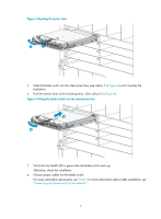
Removing the blade switch 1. Wear an ESD-preventive wrist strap and make sure it makes good skin contact and is well grounded. 2. Press the release tab to open the ejector lever. 3. Pull the ejector lever outwards slowly to take out the blade switch. Connecting the blade switch to the network Connecting the blade switch to the network through twisted pair cables You can use category-5 or above twisted pair cables to connect the 10/100/1000Base-T ports on your blade switch to the network. These ports use RJ-45 connectors and support MDI/MDI-X auto-sensing. To connect a 10/100/1000Base-T port to a peer device: 1. Plug one end of a twisted pair cable into the RJ-45 port of the blade switch. 2. Plug the other end of the twisted pair cable into the RJ-45 port of the peer device. 3. Verify the port LED for correct connection. For LED status, see "LEDs." Connecting the blade switch to the network through optical fibers WARNING! To avoid injury to your eyes, do not stare at the optical interfaces and optical fiber connectors when connecting optical fibers. You can install a transceiver module in a fiber port on the blade switch and then plug the fiber connector to the transceiver module. For more information about installing the transceiver module, see Pluggable SFP[SFP+][XFP] Transceiver Modules Installation Guide. To install a transceiver module into the port on the blade switch and the peer device: 1. Remove the dust cover of the fiber connector, and clean the end of the fiber connector. 2. Remove the dust plug of the transceiver module, plug one end of the optical fiber into the transceiver module, and plug the other end into the transceiver module in the peer device, as shown in Figure 5. The transmit port on one end must connect to the receive port on the other end. 3. Verify the port LEDs for correct connection. For more information about LED status, see "LEDs." 5
-
 1
1 -
2
-
3
-
 4
4 -
 5
5 -
 6
6 -
 7
7 -
 8
8 -
 9
9 -
 10
10 -
 11
11 -
 12
12 -
 13
13 -
 14
14 -
15
-
16
-
17
-
18
-
19
-
20
-
21
-
22
-
23
-
24
-
25
-
26
-
27
-
28
-
29
-
30
-
31
-
32
-
33
-
34
-
35
 |
 |