HP 6125G HP 6125G & 6125G/XG Blade Switches Installation Guide-6W100 - Page 18
Setting up an IRF fabric, Planning IRF fabric setup, Determining the number of IRF member devices - xg blade switch
 |
View all HP 6125G manuals
Add to My Manuals
Save this manual to your list of manuals |
Page 18 highlights
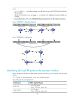
Setting up an IRF fabric You can use HP Intelligent Resilient Framework (IRF) technology to connect and virtualize HP 6125 blade switches into a virtual switch called an "IRF fabric" or "IRF virtual device" for flattened network topology, and high availability, scalability, and manageability. Planning IRF fabric setup Determining the number of IRF member devices Choose HP 6125 blade switch models and identify the number of required IRF member switches, depending on the user density and upstream bandwidth requirements. The switching capacity of an IRF fabric equals the total switching capacities of all member switches. Identifying the master switch and planning IRF member IDs IRF member switches will automatically elect a master. You can affect the election result by assigning a high member priority to the intended master switch. For more information about master election, see HP 6125 Blade Switch Series IRF Configuration Guide. Determine which switch you want to use as the master for managing all member switches in the IRF fabric. An IRF fabric has only one master switch. You configure and manage all member switches in the IRF fabric at the command line interface of the master switch. Prepare an IRF member ID assignment scheme. An IRF fabric uses member IDs to uniquely identify and manage its members, and you must assign each IRF member switch a unique member ID. Planning IRF topology and connections You can create an IRF fabric in daisy chain topology, or more reliably, ring topology. In ring topology, the failure of one IRF link does not cause the IRF fabric to split as in daisy chain topology. Rather, the IRF fabric changes to a daisy chain topology without interrupting network services. You connect the IRF member switches through IRF ports, the logical interfaces for the connections between IRF member switches. Each IRF member switch has two IRF ports: IRF-port 1 and IRF-port 2. An IRF port goes up when you bind the first member physical port to it. When connecting IRF member switches, you must connect the physical ports of IRF-port 1 on one switch to the physical ports of IRF-port 2 on its neighbor switch. The HP 6125 switches can provide 10-GE IRF connections through SFP+ ports, and you can bind several SFP+ ports to an IRF port for increased bandwidth and availability. When two 6125G or 6125G/XG switches are plugged into adjacent (side-by-side) interconnect bays of the c7000 or c3000, the internal 10-GE cross connect ports between those adjacent 6125G or 6125G/XG can be used for an IRF connection as well. 14
-
 1
1 -
2
-
3
-
4
-
5
-
6
-
7
-
8
-
9
-
10
-
11
-
12
-
 13
13 -
 14
14 -
 15
15 -
 16
16 -
 17
17 -
 18
18 -
 19
19 -
 20
20 -
 21
21 -
 22
22 -
 23
23 -
24
-
25
-
26
-
27
-
28
-
29
-
30
-
31
-
32
-
33
-
34
-
35
 |
 |