HP 6125G HP 6125G & 6125G/XG Blade Switches Installation Guide-6W100 - Page 19
Identifying physical IRF ports on the member switches, Table 3
 |
View all HP 6125G manuals
Add to My Manuals
Save this manual to your list of manuals |
Page 19 highlights
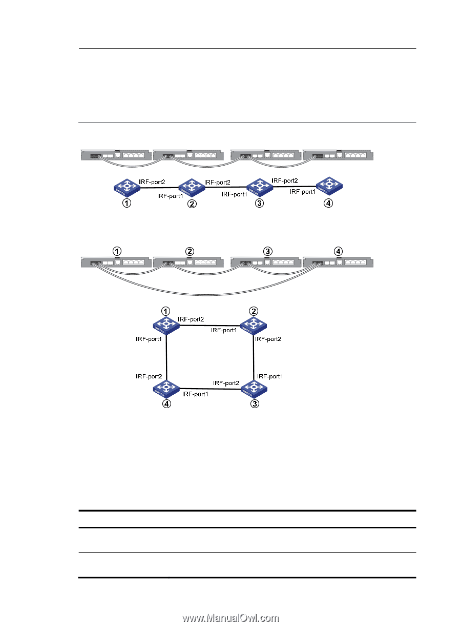
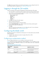
NOTE: • Figure 13 and Figure 14 show the topologies for an IRF fabric made up of HP 6125G blade switches for IRF connections. • The IRF port connections in the two figures are for illustration only, and more connection methods are available. • Any or all of the four SFP+ ports on the 6125G/XG can be used either for IRF or data connections. Figure 13 IRF fabric in daisy chain topology Figure 14 IRF fabric in ring topology Identifying physical IRF ports on the member switches Identify the physical IRF ports on the member switches according to your topology and connection scheme. Table 3 shows the physical ports that can be used for IRF connection. Table 3 Physical IRF port requirements Switch chassis HP 6125G HP 6125G/XG Candidate physical IRF ports • 2 fixed IRF/SFP ports • 1 internal 10-GE cross connect port • 4 fixed SFP+ ports • 1 internal 10-GE cross connect port 15
-
 1
1 -
2
-
3
-
4
-
5
-
6
-
7
-
8
-
9
-
10
-
11
-
12
-
13
-
 14
14 -
 15
15 -
 16
16 -
 17
17 -
 18
18 -
 19
19 -
 20
20 -
 21
21 -
 22
22 -
 23
23 -
 24
24 -
25
-
26
-
27
-
28
-
29
-
30
-
31
-
32
-
33
-
34
-
35
 |
 |