HP AD510A HP StorageWorks 1500 Modular Smart Array maintenance and service gui - Page 19
System components and LEDs, Front view
 |
UPC - 829160218625
View all HP AD510A manuals
Add to My Manuals
Save this manual to your list of manuals |
Page 19 highlights
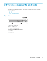
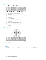
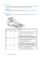
3 System components and LEDs This chapter includes figures and tables that identify system components and describe chassis and module LEDs patterns. • Front view • Rear view • Chassis and component LEDs Front view 1234 5 6 1 Unit ID button and LED (blue) 2 System fault LED (amber) 3 Heartbeat LED (blinking green) 4 Power on/Standby button (green or amber) 5 MSA1000 controller 6 Controller blank 15503 maintenance and service guide 19
-
 1
1 -
2
-
3
-
4
-
5
-
6
-
7
-
8
-
9
-
10
-
11
-
12
-
13
-
 14
14 -
 15
15 -
 16
16 -
 17
17 -
 18
18 -
 19
19 -
 20
20 -
 21
21 -
 22
22 -
 23
23 -
 24
24 -
25
-
26
-
27
-
28
-
29
-
30
-
31
-
32
-
33
-
34
-
35
-
36
-
37
-
38
-
39
-
40
-
41
-
42
-
43
-
44
-
45
-
46
-
47
-
48
-
49
-
50
-
51
-
52
-
53
-
54
-
55
-
56
-
57
-
58
-
59
-
60
-
61
-
62
-
63
-
64
-
65
-
66
-
67
-
68
-
69
-
70
-
71
-
72
-
73
-
74
-
75
-
76
-
77
-
78
-
79
-
80
-
81
-
82
-
83
-
84
-
85
-
86
-
87
-
88
-
89
-
90
-
91
-
92
-
93
-
94
-
95
-
96
-
97
-
98
-
99
-
100
-
101
-
102
-
103
-
104
-
105
-
106
-
107
-
108
-
109
-
110
-
111
-
112
-
113
-
114
-
115
-
116
-
117
-
118
-
119
-
120
 |
 |

3 System components and LEDs
This chapter includes
fi
gures and tables that identify system components and describe chassis and
module LEDs patterns.
•
Front view
•
Rear view
•
Chassis and component LEDs
Front view
1
5
6
2
3
4
15503
1
Unit ID button and LED (blue)
2
System fault LED (amber)
3
Heartbeat LED (blinking green)
4
Power on/Standby button (green or amber)
5
MSA1000 controller
6
Controller blank
maintenance and service guide
19