HP AD510A HP StorageWorks 1500 Modular Smart Array maintenance and service gui - Page 21
Slot diagram label, Chassis and component LEDs
 |
UPC - 829160218625
View all HP AD510A manuals
Add to My Manuals
Save this manual to your list of manuals |
Page 21 highlights
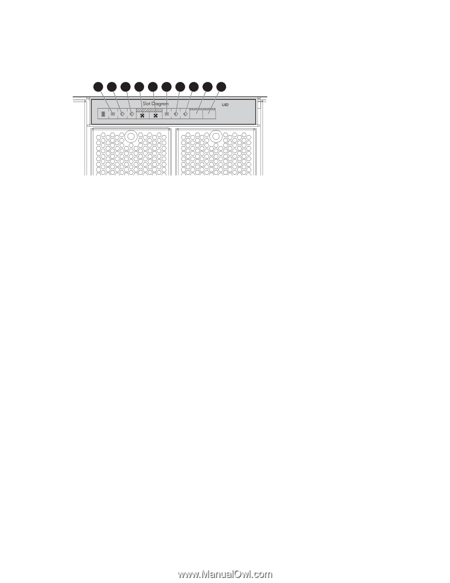
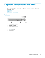
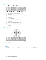
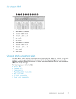
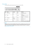
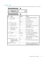
Slot diagram label 1 2 3 4 5 6 7 8 9 10 8 47 3 6 25 1 5 2 2 1 PS 2 PS 1 1 0 15523 1 Fibre Channel I/O module 2 SCSI I/O module (bus 3) 3 SCSI I/O module (bus 2) 4 Fan module 5 Fan module 6 Fibre Channel I/O module 7 SCSI I/O module (bus 1) 8 SCSI I/O module (bus 0) 9 Power supply 10 Power supply Chassis and component LEDs The MSA chassis and its modular components are equipped with LEDs. When the fault LED on any MSA component is amber, promptly determine the reason for the alert by examining the component, the messages displayed on the MSA controller LCD panel, and system event logs (such as those provided by HP Systems Insight Manager). The following sections define the LEDs: • Chassis LEDs • Controller LEDs • Hard drive LEDs • Fibre Channel I/O Module LEDs • Fan module LEDs • SCSI I/O module LEDs • Power supply module LEDs maintenance and service guide 21
-
 1
1 -
2
-
3
-
4
-
5
-
6
-
7
-
8
-
9
-
10
-
11
-
12
-
13
-
14
-
15
-
 16
16 -
 17
17 -
 18
18 -
 19
19 -
 20
20 -
 21
21 -
 22
22 -
 23
23 -
 24
24 -
 25
25 -
 26
26 -
27
-
28
-
29
-
30
-
31
-
32
-
33
-
34
-
35
-
36
-
37
-
38
-
39
-
40
-
41
-
42
-
43
-
44
-
45
-
46
-
47
-
48
-
49
-
50
-
51
-
52
-
53
-
54
-
55
-
56
-
57
-
58
-
59
-
60
-
61
-
62
-
63
-
64
-
65
-
66
-
67
-
68
-
69
-
70
-
71
-
72
-
73
-
74
-
75
-
76
-
77
-
78
-
79
-
80
-
81
-
82
-
83
-
84
-
85
-
86
-
87
-
88
-
89
-
90
-
91
-
92
-
93
-
94
-
95
-
96
-
97
-
98
-
99
-
100
-
101
-
102
-
103
-
104
-
105
-
106
-
107
-
108
-
109
-
110
-
111
-
112
-
113
-
114
-
115
-
116
-
117
-
118
-
119
-
120
 |
 |