HP ENVY 14-1000 HP ENVY 14 Notebook PC - Maintenance and Service Guide - Page 104
Universal Serial Bus USB, Double-Layer Combo Drive
 |
View all HP ENVY 14-1000 manuals
Add to My Manuals
Save this manual to your list of manuals |
Page 104 highlights
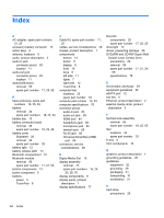
Index A AC adapter, spare part numbers 21, 25 accessory battery connector 13 action keys 6 antenna, locations 9 audio, product description 2 audio-in jack connector pinout 83 location 11 audio-out jack connector pinout 83 location 11 audio/USB board removal 55 spare part number 17, 25, 55 B base enclosure, spare part numbers 18, 25, 26 battery removal 34 spare part numbers 18, 23, 34 battery bay 13 battery connector board removal 48 spare part number 18, 26, 48 battery cover illustrated 20 removal 34 spare part number 35 battery light 12 battery release latch 13 Bluetooth compartment 10 Bluetooth module removal 56 spare part number 17, 27, 56 bottom components 13 button component 5 buttons power 5 TouchPad 8 C Cable Kit, spare part number 17, 25 cables, service considerations 28 chipset, product description 1 components bottom 13 button 5 display 9 front 10 keys 6 left side 11 lights 7 right side 12 TouchPad 8 computer feet locations 33 spare part number 33 computer part number 14, 33 computer specifications 76 connector pinout audio-in jack 83 audio-out jack 83 HDMI port 84 headphone jack 83 microphone jack 83 network jack 85 RJ-45 jack 85 Universal Serial Bus (USB) port 85 connectors, service considerations 28 D Digital Media Slot 10 display assembly removal 70 spare part numbers 16, 24, 25, 26, 70 display components 9 display panel, product description 1 display specifications 77 Door Kit components 20 spare part number 17, 20, 25 drive light 12 drives, preventing damage 29 DVD±RW and CD-RW Super Multi Double-Layer Combo Drive precautions 29 removal 59 spare part number 17, 21, 24, 59 specifications 78 E electrostatic discharge 29 equipment guidelines 32 eSATA port 12 esc key 6 Ethernet, product description 2 external media cards, product description 3 F fan/heat sink assembly removal 65 spare part number 18, 25, 65 feet locations 33 spare part number 33 fn key 6 front components 10 G graphics, product description 1 grounding guidelines 29 guidelines equipment 32 grounding 29 packaging 31 transporting 31 workstation 31 H hard drive precautions 29 94 Index
-
 1
1 -
2
-
3
-
4
-
5
-
6
-
7
-
8
-
9
-
10
-
11
-
12
-
13
-
14
-
15
-
16
-
17
-
18
-
19
-
20
-
21
-
22
-
23
-
24
-
25
-
26
-
27
-
28
-
29
-
30
-
31
-
32
-
33
-
34
-
35
-
36
-
37
-
38
-
39
-
40
-
41
-
42
-
43
-
44
-
45
-
46
-
47
-
48
-
49
-
50
-
51
-
52
-
53
-
54
-
55
-
56
-
57
-
58
-
59
-
60
-
61
-
62
-
63
-
64
-
65
-
66
-
67
-
68
-
69
-
70
-
71
-
72
-
73
-
74
-
75
-
76
-
77
-
78
-
79
-
80
-
81
-
82
-
83
-
84
-
85
-
86
-
87
-
88
-
89
-
90
-
91
-
92
-
93
-
94
-
95
-
96
-
97
-
98
-
 99
99 -
 100
100 -
 101
101 -
 102
102 -
 103
103 -
 104
104 -
 105
105 -
 106
106
 |
 |
