HP ENVY 14-1000 HP ENVY 14 Notebook PC - Maintenance and Service Guide - Page 58
Battery connector board, and the three Phillips PM2.0×3.0 screws
 |
View all HP ENVY 14-1000 manuals
Add to My Manuals
Save this manual to your list of manuals |
Page 58 highlights
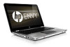
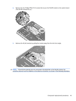
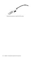
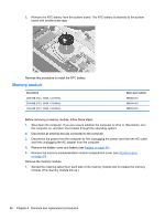
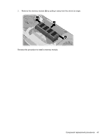
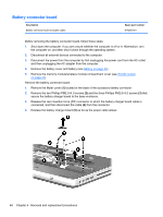
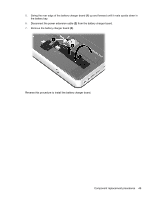
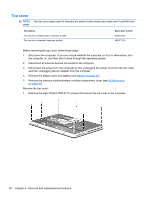
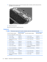
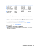
Battery connector board Description Battery connector board (includes cable) Spare part number 617265-001 Before removing the battery connector board, follow these steps: 1. Shut down the computer. If you are unsure whether the computer is off or in Hibernation, turn the computer on, and then shut it down through the operating system. 2. Disconnect all external devices connected to the computer. 3. Disconnect the power from the computer by first unplugging the power cord from the AC outlet and then unplugging the AC adapter from the computer. 4. Remove the battery cover and battery (see Battery on page 34). 5. Remove the memory module/wireless module compartment cover (see WLAN module on page 41). Remove the battery connector board: 1. Remove the Mylar cover (1) located at the base of the accessory battery connector. 2. Remove the two Phillips PM2.5×4.0 screws (2) and the three Phillips PM2.0×3.0 screws (3) that secure the battery charger board to the base enclosure. 3. Release the zero insertion force (ZIF) connector to which the battery charger board cable is connected, and then disconnect the cable (4) from the connector. 4. Release the battery charger board (5) as far as the power cable allows. 48 Chapter 4 Removal and replacement procedures
-
 1
1 -
2
-
3
-
4
-
5
-
6
-
7
-
8
-
9
-
10
-
11
-
12
-
13
-
14
-
15
-
16
-
17
-
18
-
19
-
20
-
21
-
22
-
23
-
24
-
25
-
26
-
27
-
28
-
29
-
30
-
31
-
32
-
33
-
34
-
35
-
36
-
37
-
38
-
39
-
40
-
41
-
42
-
43
-
44
-
45
-
46
-
47
-
48
-
49
-
50
-
51
-
52
-
 53
53 -
 54
54 -
 55
55 -
 56
56 -
 57
57 -
 58
58 -
 59
59 -
 60
60 -
 61
61 -
 62
62 -
 63
63 -
64
-
65
-
66
-
67
-
68
-
69
-
70
-
71
-
72
-
73
-
74
-
75
-
76
-
77
-
78
-
79
-
80
-
81
-
82
-
83
-
84
-
85
-
86
-
87
-
88
-
89
-
90
-
91
-
92
-
93
-
94
-
95
-
96
-
97
-
98
-
99
-
100
-
101
-
102
-
103
-
104
-
105
-
106
 |
 |
