HP ENVY 14-1000 HP ENVY 14 Notebook PC - Maintenance and Service Guide - Page 72
System board
 |
View all HP ENVY 14-1000 manuals
Add to My Manuals
Save this manual to your list of manuals |
Page 72 highlights
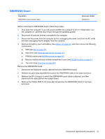
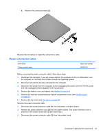
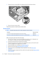
4. Release the power connector (4) from the alignment clip built into the base enclosure. 5. Remove the power connector cable. Reverse this procedure to install the power connector cable. System board NOTE: The system board spare part kit includes replacement thermal material. Description For use only on computer models equipped with an Intel Core i7 processor For use only on computer models equipped with an Intel Core i5, i3, or P6000 processor Spare part number 608365-001 608364-001 Before removing the system board, follow these steps: 1. Shut down the computer. If you are unsure whether the computer is off or in Hibernation, turn the computer on, and then shut it down through the operating system. 2. Disconnect all external devices connected to the computer. 3. Disconnect the power from the computer by first unplugging the power cord from the AC outlet and then unplugging the AC adapter from the computer. 4. Remove the battery cover and battery (see Battery on page 34). 5. Remove the hard drive (see Mass storage device on page 36). 6. Remove the memory module/wireless module compartment cover (see WLAN module on page 41). 7. Disconnect the battery charger board ribbon cable from the system board (see Battery connector board on page 48). 62 Chapter 4 Removal and replacement procedures
-
 1
1 -
2
-
3
-
4
-
5
-
6
-
7
-
8
-
9
-
10
-
11
-
12
-
13
-
14
-
15
-
16
-
17
-
18
-
19
-
20
-
21
-
22
-
23
-
24
-
25
-
26
-
27
-
28
-
29
-
30
-
31
-
32
-
33
-
34
-
35
-
36
-
37
-
38
-
39
-
40
-
41
-
42
-
43
-
44
-
45
-
46
-
47
-
48
-
49
-
50
-
51
-
52
-
53
-
54
-
55
-
56
-
57
-
58
-
59
-
60
-
61
-
62
-
63
-
64
-
65
-
66
-
 67
67 -
 68
68 -
 69
69 -
 70
70 -
 71
71 -
 72
72 -
 73
73 -
 74
74 -
 75
75 -
 76
76 -
 77
77 -
78
-
79
-
80
-
81
-
82
-
83
-
84
-
85
-
86
-
87
-
88
-
89
-
90
-
91
-
92
-
93
-
94
-
95
-
96
-
97
-
98
-
99
-
100
-
101
-
102
-
103
-
104
-
105
-
106
 |
 |
