HP ENVY 14-1000 HP ENVY 14 Notebook PC - Maintenance and Service Guide - Page 74
until it rests at an angle
 |
View all HP ENVY 14-1000 manuals
Add to My Manuals
Save this manual to your list of manuals |
Page 74 highlights
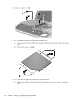
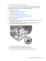
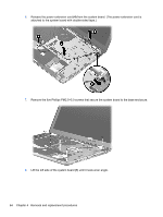
6. Release the power extension cord (4) from the system board. (The power extension cord is attached to the system board with double-sided tape.) 7. Remove the five Phillips PM2.5×5.0 screws that secure the system board to the base enclosure. 8. Lift the left side of the system board (1) until it rests at an angle. 64 Chapter 4 Removal and replacement procedures
-
 1
1 -
2
-
3
-
4
-
5
-
6
-
7
-
8
-
9
-
10
-
11
-
12
-
13
-
14
-
15
-
16
-
17
-
18
-
19
-
20
-
21
-
22
-
23
-
24
-
25
-
26
-
27
-
28
-
29
-
30
-
31
-
32
-
33
-
34
-
35
-
36
-
37
-
38
-
39
-
40
-
41
-
42
-
43
-
44
-
45
-
46
-
47
-
48
-
49
-
50
-
51
-
52
-
53
-
54
-
55
-
56
-
57
-
58
-
59
-
60
-
61
-
62
-
63
-
64
-
65
-
66
-
67
-
68
-
 69
69 -
 70
70 -
 71
71 -
 72
72 -
 73
73 -
 74
74 -
 75
75 -
 76
76 -
 77
77 -
 78
78 -
 79
79 -
80
-
81
-
82
-
83
-
84
-
85
-
86
-
87
-
88
-
89
-
90
-
91
-
92
-
93
-
94
-
95
-
96
-
97
-
98
-
99
-
100
-
101
-
102
-
103
-
104
-
105
-
106
 |
 |

6.
Release the power extension cord
(4)
from the system board. (The power extension cord is
attached to the system board with double-sided tape.)
7.
Remove the five Phillips PM2.5×5.0 screws that secure the system board to the base enclosure.
8.
Lift the left side of the system board
(1)
until it rests at an angle.
64
Chapter 4
Removal and replacement procedures