HP ENVY 14-1000 HP ENVY 14 Notebook PC - Maintenance and Service Guide - Page 53
If the WLAN antennas are not connected to the terminals on the WLAN module,
 |
View all HP ENVY 14-1000 manuals
Add to My Manuals
Save this manual to your list of manuals |
Page 53 highlights
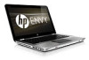
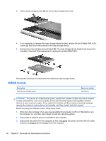
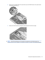
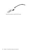
5. Remove the two Phillips PM2.0×3.0 screws that secure the WLAN module to the system board. (The WLAN module tilts up.) 6. Remove the WLAN module by pulling the module away from the slot at an angle. NOTE: If the WLAN antennas are not connected to the terminals on the WLAN module, the protective sleeves must be installed on the antenna connectors, as shown in the following illustration. Component replacement procedures 43
-
 1
1 -
2
-
3
-
4
-
5
-
6
-
7
-
8
-
9
-
10
-
11
-
12
-
13
-
14
-
15
-
16
-
17
-
18
-
19
-
20
-
21
-
22
-
23
-
24
-
25
-
26
-
27
-
28
-
29
-
30
-
31
-
32
-
33
-
34
-
35
-
36
-
37
-
38
-
39
-
40
-
41
-
42
-
43
-
44
-
45
-
46
-
47
-
 48
48 -
 49
49 -
 50
50 -
 51
51 -
 52
52 -
 53
53 -
 54
54 -
 55
55 -
 56
56 -
 57
57 -
 58
58 -
59
-
60
-
61
-
62
-
63
-
64
-
65
-
66
-
67
-
68
-
69
-
70
-
71
-
72
-
73
-
74
-
75
-
76
-
77
-
78
-
79
-
80
-
81
-
82
-
83
-
84
-
85
-
86
-
87
-
88
-
89
-
90
-
91
-
92
-
93
-
94
-
95
-
96
-
97
-
98
-
99
-
100
-
101
-
102
-
103
-
104
-
105
-
106
 |
 |

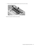
5.
Remove the two Phillips PM2.0×3.0 screws that secure the WLAN module to the system board.
(The WLAN module tilts up.)
6.
Remove the WLAN module by pulling the module away from the slot at an angle.
NOTE:
If the WLAN antennas are not connected to the terminals on the WLAN module, the
protective sleeves must be installed on the antenna connectors, as shown in the following illustration.
Component replacement procedures
43