HP ENVY 14-1000 HP ENVY 14 Notebook PC - Maintenance and Service Guide - Page 73
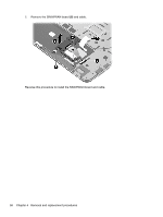
from the system board., Release the ZIF connector to which the audio/USB board cable is attached
 |
View all HP ENVY 14-1000 manuals
Add to My Manuals
Save this manual to your list of manuals |
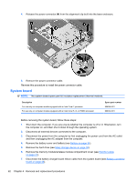
Page 73 highlights
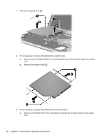
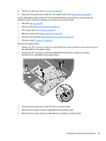
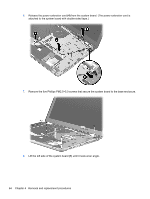
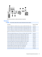
8. Remove the top cover (see Top cover on page 50). 9. Disconnect the optical drive cable from the system board (see Optical drive on page 59). When replacing the system board, be sure that the following components are removed from the defective system board and installed on the replacement system board: ● SIM (see SIM on page 35) ● WLAN module (see WLAN module on page 41) ● RTC battery (see RTC battery on page 45) ● Memory module (see Memory module on page 46) ● Fan/heat sink assembly (see Fan/heat sink assembly on page 65) ● Processor (see Processor on page 67) Remove the system board: 1. Release the ZIF connector to which the audio/USB board cable is attached, and then disconnect the cable (1) from the system board. 2. Release the ZIF connector to which the SIM/WWAN board cable is attached, and then disconnect the cable (2) from the system board. 3. Disconnect the display panel cable (1) from the system board. 4. Disconnect the power connector cable (2) from the system board. 5. Disconnect the power extension cable (3) from the battery connector board. Component replacement procedures 63
-
 1
1 -
2
-
3
-
4
-
5
-
6
-
7
-
8
-
9
-
10
-
11
-
12
-
13
-
14
-
15
-
16
-
17
-
18
-
19
-
20
-
21
-
22
-
23
-
24
-
25
-
26
-
27
-
28
-
29
-
30
-
31
-
32
-
33
-
34
-
35
-
36
-
37
-
38
-
39
-
40
-
41
-
42
-
43
-
44
-
45
-
46
-
47
-
48
-
49
-
50
-
51
-
52
-
53
-
54
-
55
-
56
-
57
-
58
-
59
-
60
-
61
-
62
-
63
-
64
-
65
-
66
-
67
-
 68
68 -
 69
69 -
 70
70 -
 71
71 -
 72
72 -
 73
73 -
 74
74 -
 75
75 -
 76
76 -
 77
77 -
 78
78 -
79
-
80
-
81
-
82
-
83
-
84
-
85
-
86
-
87
-
88
-
89
-
90
-
91
-
92
-
93
-
94
-
95
-
96
-
97
-
98
-
99
-
100
-
101
-
102
-
103
-
104
-
105
-
106
 |
 |
