HP ENVY 14-1000 HP ENVY 14 Notebook PC - Maintenance and Service Guide - Page 71
Power connector cable, from the battery connector board.
 |
View all HP ENVY 14-1000 manuals
Add to My Manuals
Save this manual to your list of manuals |
Page 71 highlights
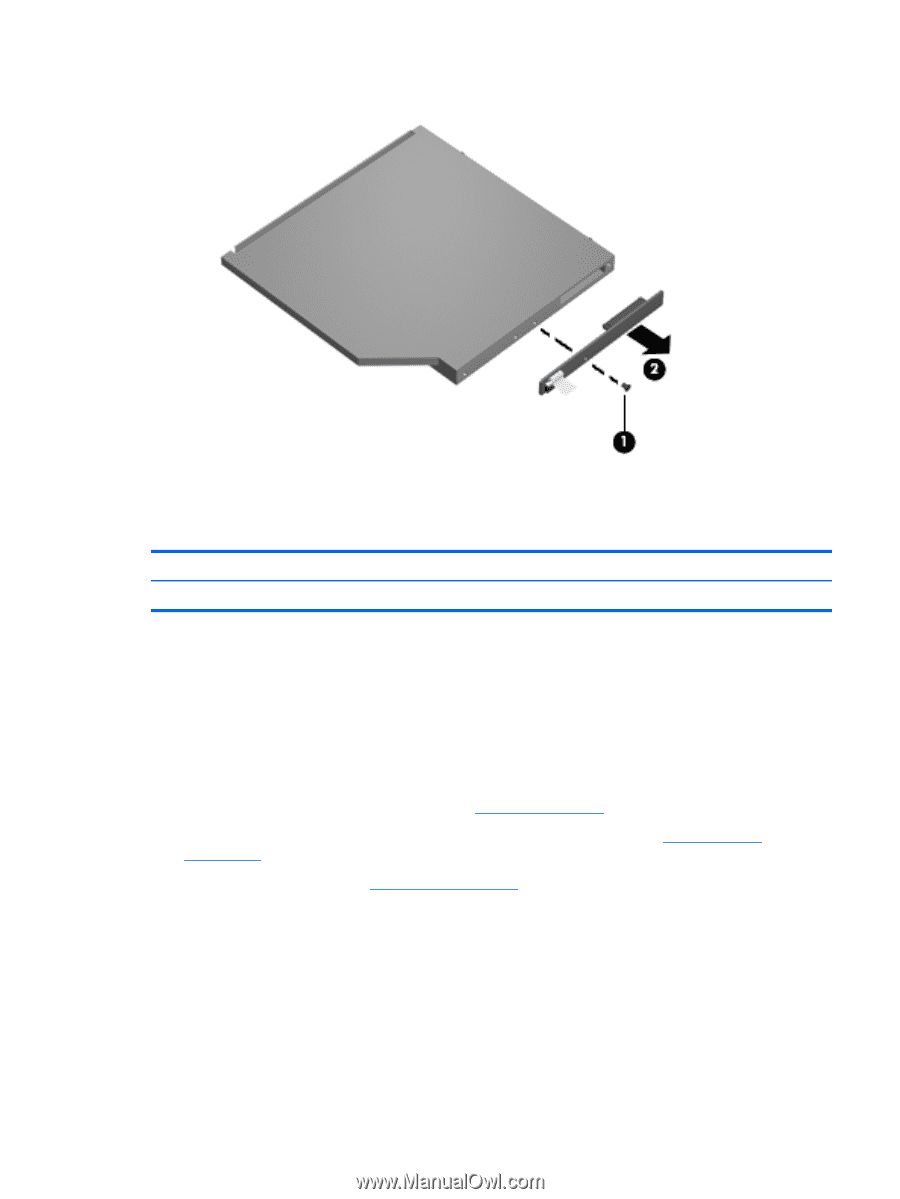
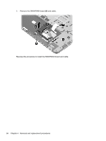
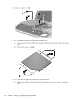
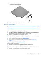
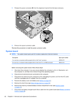
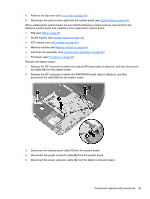
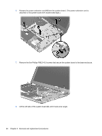
b. Remove the connector board (2). Reverse this procedure to install the optical drive cable. Power connector cable Description Power connector cable Spare part number 608380-001 Before removing the power connector cable, follow these steps: 1. Shut down the computer. If you are unsure whether the computer is off or in Hibernation, turn the computer on, and then shut it down through the operating system. 2. Disconnect all external devices connected to the computer. 3. Disconnect the power from the computer by first unplugging the power cord from the AC outlet and then unplugging the AC adapter from the computer. 4. Remove the battery cover and battery (see Battery on page 34). 5. Remove the memory module/wireless module compartment cover (see WLAN module on page 41). 6. Remove the top cover (see Top cover on page 50). Remove the power connector cable: 1. Disconnect the power extension cable (1) from the battery connector board. 2. Release the power extension cord (2) from the system board. (The power extension cord is attached to the system board with double-sided tape.) 3. Disconnect the power connector cable (3) from the system board. Component replacement procedures 61
-
 1
1 -
2
-
3
-
4
-
5
-
6
-
7
-
8
-
9
-
10
-
11
-
12
-
13
-
14
-
15
-
16
-
17
-
18
-
19
-
20
-
21
-
22
-
23
-
24
-
25
-
26
-
27
-
28
-
29
-
30
-
31
-
32
-
33
-
34
-
35
-
36
-
37
-
38
-
39
-
40
-
41
-
42
-
43
-
44
-
45
-
46
-
47
-
48
-
49
-
50
-
51
-
52
-
53
-
54
-
55
-
56
-
57
-
58
-
59
-
60
-
61
-
62
-
63
-
64
-
65
-
 66
66 -
 67
67 -
 68
68 -
 69
69 -
 70
70 -
 71
71 -
 72
72 -
 73
73 -
 74
74 -
 75
75 -
 76
76 -
77
-
78
-
79
-
80
-
81
-
82
-
83
-
84
-
85
-
86
-
87
-
88
-
89
-
90
-
91
-
92
-
93
-
94
-
95
-
96
-
97
-
98
-
99
-
100
-
101
-
102
-
103
-
104
-
105
-
106
 |
 |