HP ENVY 14-1000 HP ENVY 14 Notebook PC - Maintenance and Service Guide - Page 76
that services it, Thermal paste is used on the processor
 |
View all HP ENVY 14-1000 manuals
Add to My Manuals
Save this manual to your list of manuals |
Page 76 highlights
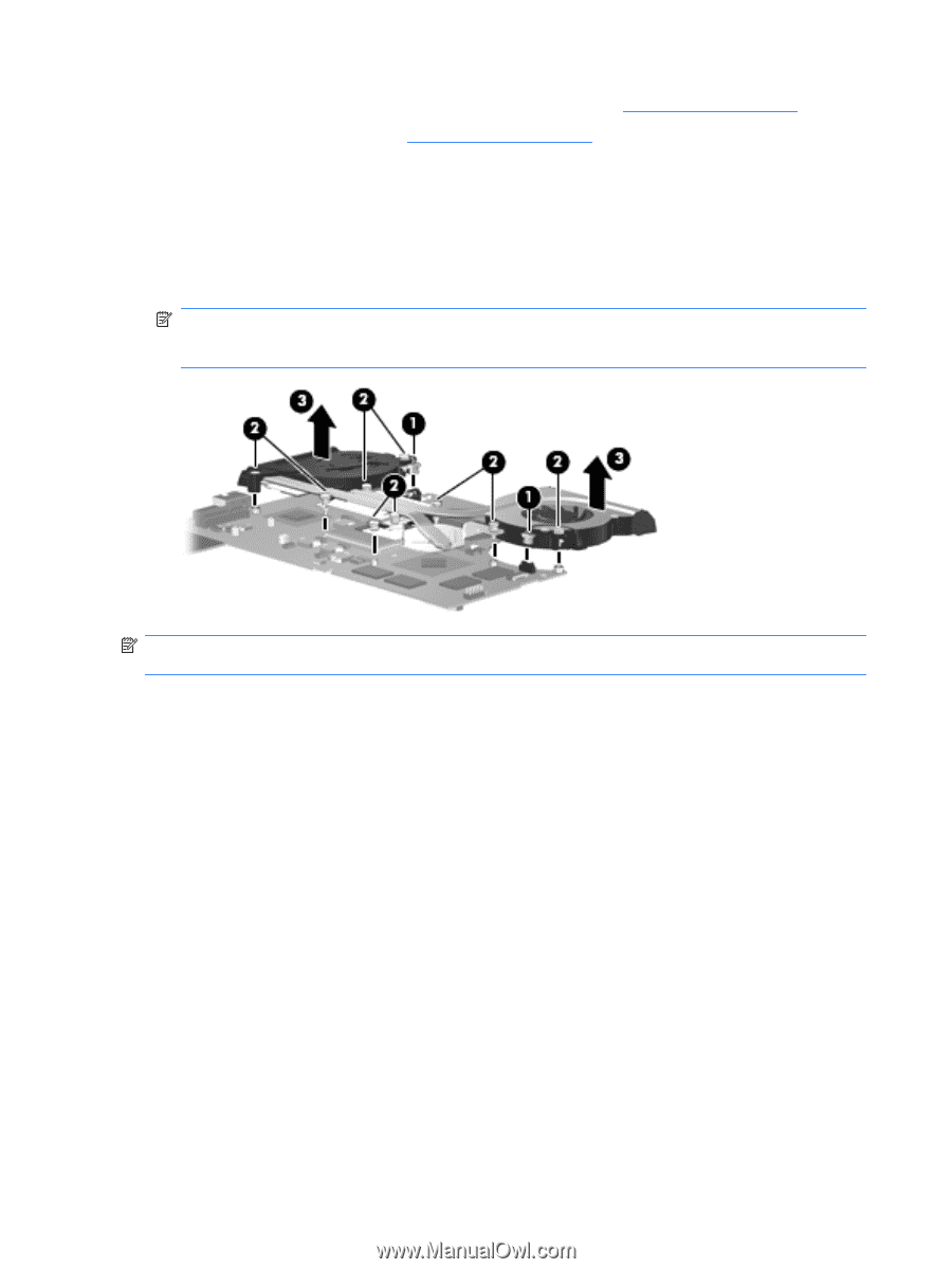
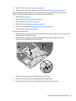
9. Disconnect the optical drive cable from the system board (see Optical drive on page 59). 10. Remove the system board (see System board on page 62). Remove the fan/heat sink assembly: 1. Turn the system board upside down with the front toward you. 2. Disconnect the two fan cables (1) from the system board. 3. Loosen the nine captive screws (2) that secure the fan/heat sink assembly to the system board. 4. Remove the fan/heat sink assembly (3). NOTE: Due to the adhesive quality of the thermal material located between the fan/heat sink assembly and system board components, it may be necessary to move the fan/heat sink assembly from side to side to detach it. NOTE: The thermal material must be thoroughly cleaned from the surfaces of the fan/heat sink assembly and the processor each time the fan/heat sink assembly is removed. ● Thermal paste is used on the processor (1) and the heat sink section (2) that services it ● A thermal pad is used on the PCH chip (3) and the heat sink section (4) that services it ● Thermal paste is used on the graphics subsystem chip (5) and the heat sink section (6) that services it Replacement thermal material is included with all fan/heat sink assembly, system board, and processor spare part kits. 66 Chapter 4 Removal and replacement procedures
-
 1
1 -
2
-
3
-
4
-
5
-
6
-
7
-
8
-
9
-
10
-
11
-
12
-
13
-
14
-
15
-
16
-
17
-
18
-
19
-
20
-
21
-
22
-
23
-
24
-
25
-
26
-
27
-
28
-
29
-
30
-
31
-
32
-
33
-
34
-
35
-
36
-
37
-
38
-
39
-
40
-
41
-
42
-
43
-
44
-
45
-
46
-
47
-
48
-
49
-
50
-
51
-
52
-
53
-
54
-
55
-
56
-
57
-
58
-
59
-
60
-
61
-
62
-
63
-
64
-
65
-
66
-
67
-
68
-
69
-
70
-
 71
71 -
 72
72 -
 73
73 -
 74
74 -
 75
75 -
 76
76 -
 77
77 -
 78
78 -
 79
79 -
 80
80 -
 81
81 -
82
-
83
-
84
-
85
-
86
-
87
-
88
-
89
-
90
-
91
-
92
-
93
-
94
-
95
-
96
-
97
-
98
-
99
-
100
-
101
-
102
-
103
-
104
-
105
-
106
 |
 |