HP ENVY 14-1000 HP ENVY 14 Notebook PC - Maintenance and Service Guide - Page 80
Display assembly, Disconnect the wireless antenna cables
 |
View all HP ENVY 14-1000 manuals
Add to My Manuals
Save this manual to your list of manuals |
Page 80 highlights
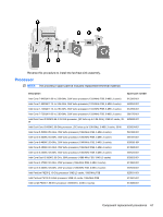
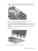
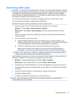
Reverse this procedure to install the speakers. Display assembly NOTE: The display assembly spare part kit includes a display panel cable, webcam/microphone module and cable, 2 WLAN antenna cables and transceivers,and 2 WWAN antenna cables and transceivers. Description 14.5-in, LED, HD, AntiGlare, flush glass SVA display assembly for use only on Beats Edition computer models 14.5-in, LED, HD, AntiGlare, flush glass SVA display assembly for use only on standard computer models 14.5-in, LED, HD+, AntiGlare, flush glass WVA display assembly for use only on standard computer models Spare part number 619399-001 616270-001 608366-001 Before removing the display assembly, follow these steps: 1. Shut down the computer. If you are unsure whether the computer is off or in Hibernation, turn the computer on, and then shut it down through the operating system. 2. Disconnect all external devices connected to the computer. 3. Disconnect the power from the computer by first unplugging the power cord from the AC outlet and then unplugging the AC adapter from the computer. 4. Remove the battery cover and battery (see Battery on page 34). 5. Remove the memory module/wireless module compartment cover (see WLAN module on page 41). 6. Remove the top cover (see Top cover on page 50). Remove the display assembly: 1. Close the computer. 2. Turn the computer upside down, with the front toward you. 3. Disconnect the wireless antenna cables (1) from the WWAN and WLAN modules. 4. Release the wireless antenna cables from the routing clips (2) built into the base enclosure. 5. Release the grounding tape (3) that secures the WWAN antenna cables to the base enclosure. 70 Chapter 4 Removal and replacement procedures
-
 1
1 -
2
-
3
-
4
-
5
-
6
-
7
-
8
-
9
-
10
-
11
-
12
-
13
-
14
-
15
-
16
-
17
-
18
-
19
-
20
-
21
-
22
-
23
-
24
-
25
-
26
-
27
-
28
-
29
-
30
-
31
-
32
-
33
-
34
-
35
-
36
-
37
-
38
-
39
-
40
-
41
-
42
-
43
-
44
-
45
-
46
-
47
-
48
-
49
-
50
-
51
-
52
-
53
-
54
-
55
-
56
-
57
-
58
-
59
-
60
-
61
-
62
-
63
-
64
-
65
-
66
-
67
-
68
-
69
-
70
-
71
-
72
-
73
-
74
-
 75
75 -
 76
76 -
 77
77 -
 78
78 -
 79
79 -
 80
80 -
 81
81 -
 82
82 -
 83
83 -
 84
84 -
 85
85 -
86
-
87
-
88
-
89
-
90
-
91
-
92
-
93
-
94
-
95
-
96
-
97
-
98
-
99
-
100
-
101
-
102
-
103
-
104
-
105
-
106
 |
 |