HP Pavilion dv4-2100 HP Pavilion dv4 Entertainment PC - Maintenance and Servic - Page 137
Hard Drive Hardware Kit MultiBay, spare part number
 |
View all HP Pavilion dv4-2100 manuals
Add to My Manuals
Save this manual to your list of manuals |
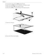
Page 137 highlights
INDEX HDMI port 9-3 headphone jack 9-1 microphone jack 9-1 modem jack 9-4 monitor port 9-2 network jack 9-5 RJ-11 jack 9-4 RJ-45 jack 9-5 USB port 9-6 connectors, service considerations 4-1 consumer infrared lens 2-6 D Diagnostics menu, Setup Utility 5-4 Digital Media slot light 2-9 location 2-9 display assembly removal 4-26 spare part numbers 3-3, 4-26 display bezel removal 4-28 spare part number 3-8, 3-15, 4-28 display cable removal 4-30 spare part number 3-8, 4-30 display components, recycling 11-1 display enclosure, spare part number 3-8, 3-15 display hinge removal 4-30 spare part number 3-8, 3-12, 4-30 display inverter, removal 11-2 display lid cable, spare part number 3-12 display panel product description 1-1 removal 4-29 spare part number 3-8, 3-16, 4-29 displaying system information 5-2 docking product description 1-4 drive light 2-2, 2-6 drives, boot order 5-4 DVD±RW and CD-RW SuperMulti Double-Layer Combo Drive with LightScribe precautions 4-2 removal 4-18 spare part number 3-16, 4-18 specifications 6-5 E electrostatic discharge 4-2 equipment guidelines 4-4 eSATA/USB port 2-9 esc key 2-4 INDEX-2 Ethernet product description 1-3 exiting Setup Utility 5-3 expansion port 2-9 ExpressCard remote, spare part numbers 3-11 ExpressCard slot 2-9 ExpressCard slot bezel 3-9 ExpressCard slot bezel, illustrated 3-9 external media card product description 1-3 external monitor port connector pinout 9-2 illustrated 2-9 F f11 key 8-6 fan removal 4-53 spare part number 3-4, 3-12, 4-53 fan always on 5-4 feet locations 4-6 spare part number 4-6 Fingerprint Reader 2-3 removal 4-36 spare part number 3-3, 3-12 fn key 2-4 front components 2-6 function keys 2-4 G graphics product description 1-1 grounding equipment and methods 4-2 H Hard Drive bay 2-10 cover 3-9 precautions 4-2 product description 1-2 removal 4-8 self test 5-4 spare part numbers 3-7, 3-10, 3-12, 3-13, 3-16, 4-8 specifications 6-3 Hard Drive blank, spare part numbers 3-10 Hard Drive bracket, removal 4-9 Hard Drive Hardware Kit MultiBay, spare part number 3-12, 4-8 Hard Drive Hardware Kit, spare part numbers 3-10, 3-12, 4-8 HDMI port connector pinout 9-3 location 2-9 Maintenance and Service Guide
-
 1
1 -
2
-
3
-
4
-
5
-
6
-
7
-
8
-
9
-
10
-
11
-
12
-
13
-
14
-
15
-
16
-
17
-
18
-
19
-
20
-
21
-
22
-
23
-
24
-
25
-
26
-
27
-
28
-
29
-
30
-
31
-
32
-
33
-
34
-
35
-
36
-
37
-
38
-
39
-
40
-
41
-
42
-
43
-
44
-
45
-
46
-
47
-
48
-
49
-
50
-
51
-
52
-
53
-
54
-
55
-
56
-
57
-
58
-
59
-
60
-
61
-
62
-
63
-
64
-
65
-
66
-
67
-
68
-
69
-
70
-
71
-
72
-
73
-
74
-
75
-
76
-
77
-
78
-
79
-
80
-
81
-
82
-
83
-
84
-
85
-
86
-
87
-
88
-
89
-
90
-
91
-
92
-
93
-
94
-
95
-
96
-
97
-
98
-
99
-
100
-
101
-
102
-
103
-
104
-
105
-
106
-
107
-
108
-
109
-
110
-
111
-
112
-
113
-
114
-
115
-
116
-
117
-
118
-
119
-
120
-
121
-
122
-
123
-
124
-
125
-
126
-
127
-
128
-
129
-
130
-
131
-
 132
132 -
 133
133 -
 134
134 -
 135
135 -
 136
136 -
 137
137 -
 138
138 -
 139
139 -
 140
140 -
 141
141
 |
 |