HP Pavilion dv4-2100 HP Pavilion dv4 Entertainment PC - Maintenance and Servic - Page 94
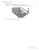
Release the system board, until it rests at an angle.
 |
View all HP Pavilion dv4-2100 manuals
Add to My Manuals
Save this manual to your list of manuals |
Page 94 highlights
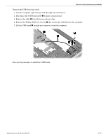
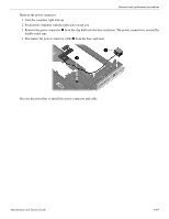
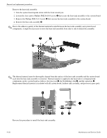
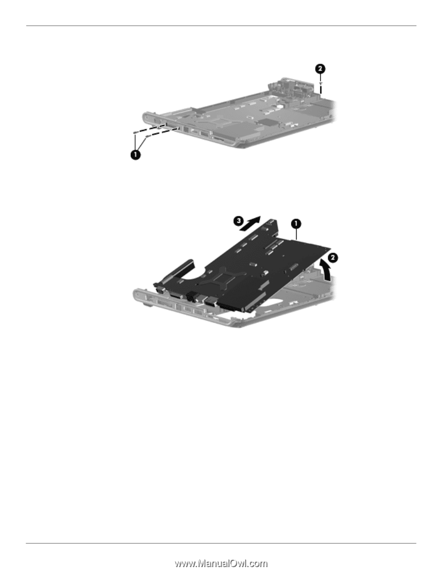
Removal and replacement procedures 4. Remove the two Phillips PM1.5×9.0 screws 1 and the Phillips PM2.5×3.0 screw 2 that secure the system board to the computer. 5. Use the optical drive connector 1 to lift the right side of the system board 2 until it rests at an angle. 6. Release the system board 3 by sliding it to the right at an angle until the connectors on the left side of the system board disengage from the base enclosure, and then remove the system board. Reverse this procedure to install the system board. 4-52 Maintenance and Service Guide
-
 1
1 -
2
-
3
-
4
-
5
-
6
-
7
-
8
-
9
-
10
-
11
-
12
-
13
-
14
-
15
-
16
-
17
-
18
-
19
-
20
-
21
-
22
-
23
-
24
-
25
-
26
-
27
-
28
-
29
-
30
-
31
-
32
-
33
-
34
-
35
-
36
-
37
-
38
-
39
-
40
-
41
-
42
-
43
-
44
-
45
-
46
-
47
-
48
-
49
-
50
-
51
-
52
-
53
-
54
-
55
-
56
-
57
-
58
-
59
-
60
-
61
-
62
-
63
-
64
-
65
-
66
-
67
-
68
-
69
-
70
-
71
-
72
-
73
-
74
-
75
-
76
-
77
-
78
-
79
-
80
-
81
-
82
-
83
-
84
-
85
-
86
-
87
-
88
-
 89
89 -
 90
90 -
 91
91 -
 92
92 -
 93
93 -
 94
94 -
 95
95 -
 96
96 -
 97
97 -
 98
98 -
 99
99 -
100
-
101
-
102
-
103
-
104
-
105
-
106
-
107
-
108
-
109
-
110
-
111
-
112
-
113
-
114
-
115
-
116
-
117
-
118
-
119
-
120
-
121
-
122
-
123
-
124
-
125
-
126
-
127
-
128
-
129
-
130
-
131
-
132
-
133
-
134
-
135
-
136
-
137
-
138
-
139
-
140
-
141
 |
 |
4–52
Maintenance and Service Guide
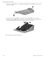
Removal and replacement procedures
4. Remove the two Phillips PM1.5×9.0 screws
1
and the Phillips PM2.5×3.0 screw
2
that secure the system
board to the computer.
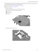
5. Use the optical drive connector
1
to lift the right side of the system board
2
until it rests at an angle.
6. Release the system board
3
by sliding it to the right at an angle until the connectors on the left side of the
system board disengage from the base enclosure, and then remove the system board.
Reverse this procedure to install the system board.