HP Pavilion dv4-2100 HP Pavilion dv4 Entertainment PC - Maintenance and Servic - Page 95
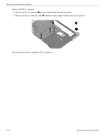
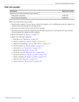
RJ-11 connector (select models only
 |
View all HP Pavilion dv4-2100 manuals
Add to My Manuals
Save this manual to your list of manuals |
Page 95 highlights
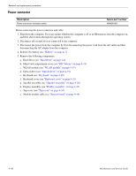
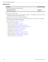
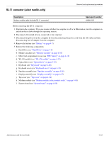
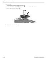
RJ-11 connector (select models only) Removal and replacement procedures Description Modem module cable (includes RJ-11 connector) Spare part number 494981-001 Before removing the RJ-11 connector: 1. Shut down the computer. If you are unsure whether the computer is off or in Hibernation, turn the computer on, and then shut it down through the operating system. 2. Disconnect all external devices connected to the computer. 3. Disconnect the power from the computer by first disconnecting the power cord from the AC outlet and then disconnecting the AC adapter from the computer. 4. Remove the battery (see "Battery" on page 4-7). 5. Remove the following components: a. Hard Drive (see "Hard Drive" on page 4-8) b. Memory module (see "Memory module" on page 4-10) c. Mini Card compartment cover (see "RTC battery" on page 4-12) d. WLAN module (see "WLAN module" on page 4-15) e. Optical drive (see "Optical drive" on page 4-19) f. Keyboard (see "Keyboard" on page 4-20) g. Keyboard cover (see "Keyboard cover" on page 4-23) h. Speaker assembly (see "Speaker assembly" on page 4-26) i. Display assembly (see "Display assembly" on page 4-27) j. Top cover (see "Top cover" on page 4-34) k. Modem module (see "Modem module (select models only)." on page 4-40) l. System board (see "System board" on page 4-50) Maintenance and Service Guide 4-53
-
 1
1 -
2
-
3
-
4
-
5
-
6
-
7
-
8
-
9
-
10
-
11
-
12
-
13
-
14
-
15
-
16
-
17
-
18
-
19
-
20
-
21
-
22
-
23
-
24
-
25
-
26
-
27
-
28
-
29
-
30
-
31
-
32
-
33
-
34
-
35
-
36
-
37
-
38
-
39
-
40
-
41
-
42
-
43
-
44
-
45
-
46
-
47
-
48
-
49
-
50
-
51
-
52
-
53
-
54
-
55
-
56
-
57
-
58
-
59
-
60
-
61
-
62
-
63
-
64
-
65
-
66
-
67
-
68
-
69
-
70
-
71
-
72
-
73
-
74
-
75
-
76
-
77
-
78
-
79
-
80
-
81
-
82
-
83
-
84
-
85
-
86
-
87
-
88
-
89
-
 90
90 -
 91
91 -
 92
92 -
 93
93 -
 94
94 -
 95
95 -
 96
96 -
 97
97 -
 98
98 -
 99
99 -
 100
100 -
101
-
102
-
103
-
104
-
105
-
106
-
107
-
108
-
109
-
110
-
111
-
112
-
113
-
114
-
115
-
116
-
117
-
118
-
119
-
120
-
121
-
122
-
123
-
124
-
125
-
126
-
127
-
128
-
129
-
130
-
131
-
132
-
133
-
134
-
135
-
136
-
137
-
138
-
139
-
140
-
141
 |
 |