HP Pavilion dv4-2100 HP Pavilion dv4 Entertainment PC - Maintenance and Servic - Page 71
and the bottom edge, the left and right sides
 |
View all HP Pavilion dv4-2100 manuals
Add to My Manuals
Save this manual to your list of manuals |
Page 71 highlights
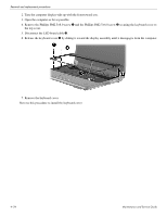
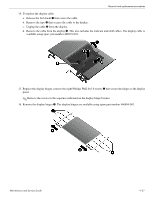
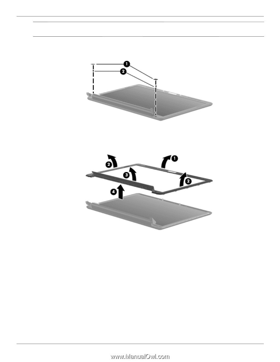
Removal and replacement procedures Ä CAUTION: Support the display assembly when removing the following screws. Failure to support the display assembly can result in damage to the display assembly and other computer components. 7. Remove the Mylar screw covers 1 and the two Phillips PM2.5×5.0 screws 2 on the display bezel lower edge.The display mylar screw covers are included in the Display Rubber Kit, spare part number 486874-001. 8. Flex the inside edges of the top edge 1, the left and right sides 2, and the bottom edge 3 of the display bezel until the bezel disengages from the display enclosure. 9. Remove the display bezel 4. The display bezel is available using spare part number 573197-001. Maintenance and Service Guide 4-29
-
 1
1 -
2
-
3
-
4
-
5
-
6
-
7
-
8
-
9
-
10
-
11
-
12
-
13
-
14
-
15
-
16
-
17
-
18
-
19
-
20
-
21
-
22
-
23
-
24
-
25
-
26
-
27
-
28
-
29
-
30
-
31
-
32
-
33
-
34
-
35
-
36
-
37
-
38
-
39
-
40
-
41
-
42
-
43
-
44
-
45
-
46
-
47
-
48
-
49
-
50
-
51
-
52
-
53
-
54
-
55
-
56
-
57
-
58
-
59
-
60
-
61
-
62
-
63
-
64
-
65
-
 66
66 -
 67
67 -
 68
68 -
 69
69 -
 70
70 -
 71
71 -
 72
72 -
 73
73 -
 74
74 -
 75
75 -
 76
76 -
77
-
78
-
79
-
80
-
81
-
82
-
83
-
84
-
85
-
86
-
87
-
88
-
89
-
90
-
91
-
92
-
93
-
94
-
95
-
96
-
97
-
98
-
99
-
100
-
101
-
102
-
103
-
104
-
105
-
106
-
107
-
108
-
109
-
110
-
111
-
112
-
113
-
114
-
115
-
116
-
117
-
118
-
119
-
120
-
121
-
122
-
123
-
124
-
125
-
126
-
127
-
128
-
129
-
130
-
131
-
132
-
133
-
134
-
135
-
136
-
137
-
138
-
139
-
140
-
141
 |
 |
Removal and replacement procedures
Maintenance and Service Guide
4–29
Ä
CAUTION:
Support the display assembly when removing the following screws. Failure to support the display
assembly can result in damage to the display assembly and other computer components.
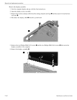
7. Remove the Mylar screw covers
1
and the two Phillips PM2.5×5.0 screws
2
on the display bezel lower
edge.The display mylar screw covers are included in the Display Rubber Kit, spare part number 486874-001.
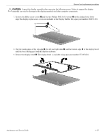
8. Flex the inside edges of the top edge
1
, the left and right sides
2
, and the bottom edge
3
of the display bezel
until the bezel disengages from the display enclosure.
9. Remove the display bezel
4
. The display bezel is available using spare part number 573197-001.