HP Pavilion dv4-2100 HP Pavilion dv4 Entertainment PC - Maintenance and Servic - Page 98
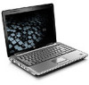
the Northbridge chip
 |
View all HP Pavilion dv4-2100 manuals
Add to My Manuals
Save this manual to your list of manuals |
Page 98 highlights
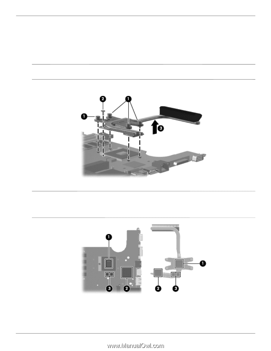
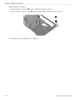
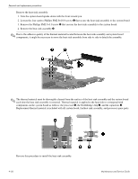
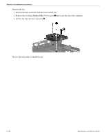
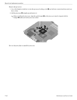
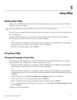
Removal and replacement procedures Remove the heat sink assembly: 1. Turn the system board upside down with the front toward you. 2. Loosen the four captive Phillips PM2.0×10.0 screws 1 that secure the heat sink assembly to the system board. 3. Remove the Phillips PM2.5×3.0 screw 2 that secures the heat sink assembly to the system board. 4. Remove the heat sink assembly 3. ✎ Due to the adhesive quality of the thermal material located between the heat sink assembly and system board components, it might be necessary to move the heat sink assembly from side to side to detach the assembly. ✎ The thermal material must be thoroughly cleaned from the surface of the heat sink assembly and the system board each time the heat sink assembly is removed. Thermal material is applied to the heat sink to correspond with components on the system board as follows: the processor 1, the Northbridge chip 2, and the capacitors 3. Replacement thermal material is included with all system board, fan/heat sink assembly, and processor spare parts. Reverse this procedure to install the heat sink assembly. 4-56 Maintenance and Service Guide
-
 1
1 -
2
-
3
-
4
-
5
-
6
-
7
-
8
-
9
-
10
-
11
-
12
-
13
-
14
-
15
-
16
-
17
-
18
-
19
-
20
-
21
-
22
-
23
-
24
-
25
-
26
-
27
-
28
-
29
-
30
-
31
-
32
-
33
-
34
-
35
-
36
-
37
-
38
-
39
-
40
-
41
-
42
-
43
-
44
-
45
-
46
-
47
-
48
-
49
-
50
-
51
-
52
-
53
-
54
-
55
-
56
-
57
-
58
-
59
-
60
-
61
-
62
-
63
-
64
-
65
-
66
-
67
-
68
-
69
-
70
-
71
-
72
-
73
-
74
-
75
-
76
-
77
-
78
-
79
-
80
-
81
-
82
-
83
-
84
-
85
-
86
-
87
-
88
-
89
-
90
-
91
-
92
-
 93
93 -
 94
94 -
 95
95 -
 96
96 -
 97
97 -
 98
98 -
 99
99 -
 100
100 -
 101
101 -
 102
102 -
 103
103 -
104
-
105
-
106
-
107
-
108
-
109
-
110
-
111
-
112
-
113
-
114
-
115
-
116
-
117
-
118
-
119
-
120
-
121
-
122
-
123
-
124
-
125
-
126
-
127
-
128
-
129
-
130
-
131
-
132
-
133
-
134
-
135
-
136
-
137
-
138
-
139
-
140
-
141
 |
 |