HP Pavilion dv4-2100 HP Pavilion dv4 Entertainment PC - Maintenance and Servic - Page 59
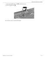
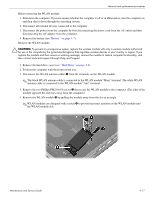
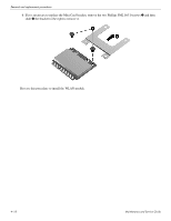
that secure the WLAN module to the computer. The edge of
 |
View all HP Pavilion dv4-2100 manuals
Add to My Manuals
Save this manual to your list of manuals |
Page 59 highlights
Removal and replacement procedures Before removing the WLAN module: 1. Shut down the computer. If you are unsure whether the computer is off or in Hibernation, turn the computer on, and then shut it down through the operating system. 2. Disconnect all external devices connected to the computer. 3. Disconnect the power from the computer by first disconnecting the power cord from the AC outlet and then disconnecting the AC adapter from the computer. 4. Remove the battery (see "Battery" on page 4-7). Remove the WLAN module: Ä CAUTION: To prevent an unresponsive system, replace the wireless module with only a wireless module authorized for use in the computer by the governmental agency that regulates wireless devices in your country or region. If you replace the module and then receive a warning message, remove the module to restore computer functionality, and then contact technical support through Help and Support. 1. Remove the hard drive cover (see "Hard Drive" on page 4-8). 2. Position the computer with the front toward you. 3. Disconnect the WLAN antenna cables 1 from the terminals on the WLAN module. ✎ The black WLAN antenna cable is connected to the WLAN module "Main" terminal. The white WLAN antenna cable is connected to the WLAN module "Aux" terminal. 4. Remove the two Phillips PM2.0×4.0 screws 2 that secure the WLAN module to the computer. (The edge of the module opposite the slot rises away from the computer.) 5. Remove the WLAN module 3 by pulling the module away from the slot at an angle. ✎ WLAN modules are designed with a notch 4 to prevent incorrect insertion of the WLAN module into the WLAN module slot. Maintenance and Service Guide 4-17
-
 1
1 -
2
-
3
-
4
-
5
-
6
-
7
-
8
-
9
-
10
-
11
-
12
-
13
-
14
-
15
-
16
-
17
-
18
-
19
-
20
-
21
-
22
-
23
-
24
-
25
-
26
-
27
-
28
-
29
-
30
-
31
-
32
-
33
-
34
-
35
-
36
-
37
-
38
-
39
-
40
-
41
-
42
-
43
-
44
-
45
-
46
-
47
-
48
-
49
-
50
-
51
-
52
-
53
-
 54
54 -
 55
55 -
 56
56 -
 57
57 -
 58
58 -
 59
59 -
 60
60 -
 61
61 -
 62
62 -
 63
63 -
 64
64 -
65
-
66
-
67
-
68
-
69
-
70
-
71
-
72
-
73
-
74
-
75
-
76
-
77
-
78
-
79
-
80
-
81
-
82
-
83
-
84
-
85
-
86
-
87
-
88
-
89
-
90
-
91
-
92
-
93
-
94
-
95
-
96
-
97
-
98
-
99
-
100
-
101
-
102
-
103
-
104
-
105
-
106
-
107
-
108
-
109
-
110
-
111
-
112
-
113
-
114
-
115
-
116
-
117
-
118
-
119
-
120
-
121
-
122
-
123
-
124
-
125
-
126
-
127
-
128
-
129
-
130
-
131
-
132
-
133
-
134
-
135
-
136
-
137
-
138
-
139
-
140
-
141
 |
 |